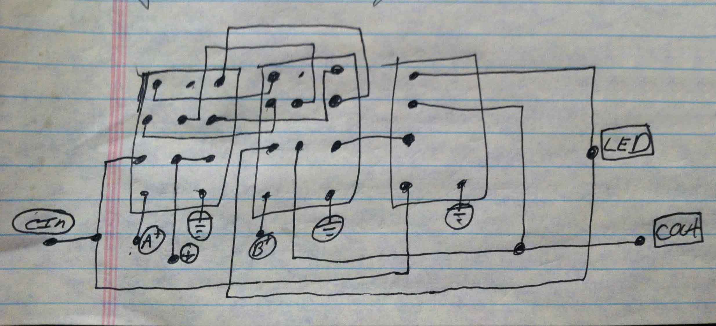
The Full-Adder with Carry
This is the basic component of binary calculations. If you need a primer on binary mathematics
Click Here. I started with this video. He put's a schematic
in the video after the demonstration, and it shows that he uses five relays for the logic circuit. After some consideration, I though I might be
able to reduce the number of relays used. It took me a long while but I finally got it down to 4 relays. In my excitement I scoured the internet
to see if anyone had done that yet. yup. In fact, here is a site where they did it in 3!!!
CLICK HERE
The above link is a fantastic site, with quite a few genius circuits. There is also a bi-polar adder that will produce negatives as well, that
was developed in the early 40's in Germany worth checking out. In the end, I engineered my own 3-relay design. The one from the site above, uses 1,
2-pole, 1 3-pole, and 1 4-pole relay. My design uses 2 3-pole relays, and 1 single pole relay. cheaper components, potentially less current draw
(which means longer bit lengths are possible),and a smaller foot print.
Note: 05/03/2016 There is an ingenious relay computer being developed on Hackaday using Konrad Zuse's two relay design! Though my above design is uses the fewest poles and relays for a floating design (not pulled to gnd when disconnected), this non-floating adder design, I believe is superior if your architecture can implement it.
16-Bit Relay Computer -
Yann Guidon
The above image is a mock-up board for the relay 1-bit adder. I actually think that my original drawing is a little easier to
understand. (At least for me.)
It is also worth mentioning that the first bit does not need to except a carry signal, there for in an array of multiple bits, the first bit
only needs two relays to preform the A-B addition.

