Memory Modules
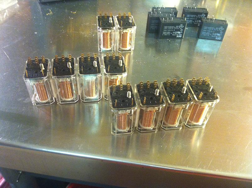
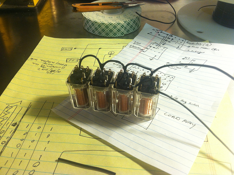
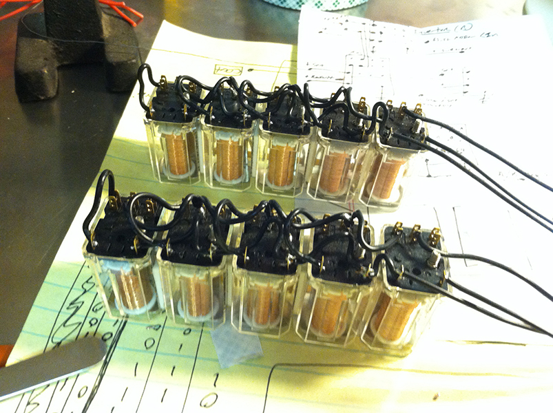
The memory in this calculator is made by simply creating a self-maintaining latch circuit in each relay. Each relay represents a single
bit. The on state represents a logical 1, the off state represents a logical 0. This circuit configuration is found in many
different appliances where you push one button to start a process and break the circuit with another switch to end the process. A Commercial
coffee grinder at a grocery store is a good example; where the button is pressed to start the grinder, but when the bag is removed, the grinder
is stopped.
This circuit works by taking the common pin from one of the poles of the relay and connecting it to the positive side of the relay coil. then,
by taking the Normally Open pin and connecting it to a voltage source that can be broken, when the coil is initially energized, it will
remain on until that "latch pole" is broken.
It's easy to make memory this way because now I can flash the relays I wish to flip to a logical 1 and they maintain themselves. Further,
to clear a bank of them, all I need to do is momentarily kill the current to the latch poles.
I have 4 switches that I set the binary value of a number with (1,2,4,8 not a very powerful calculator) these outputs are directed to a 4PDT
relay that will direct that information to either the A register or the B register. After I have selected which register I wish
to input the data into, there is a "set" relay that will load (at the flip of a momentary switch) the data into the registers all at once.
The output from each Bit of memory is simply a pull to high (12 volts) if there is a bit present.
The basic register architecture is the same for both the A and the B memory registers, there are differences however. To allow the adder to also
subtract, I have created an inverter circuit (complement) in the b register. Thereby flipping a logical 1 to a 0 and vise versa. This circuit also
adds a carry to the first bit adder (also needed for subtraction operations).
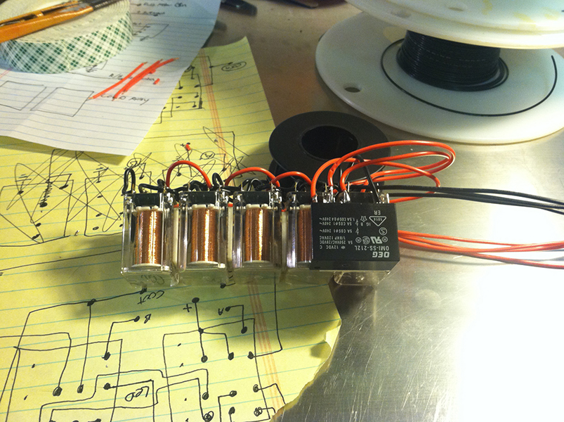
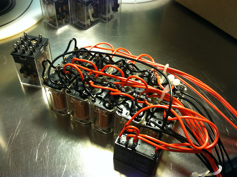
Below are pictures of the inverter relay attached to the B register. it is a double throw relay that directs the high (12 volts) to either the
Normally Open contact on the memory relay (standard output), or the Normally Closed contact of the relay (inverted output).
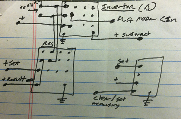
Below, is a drawing of the inverter, and clear circuits.
There are also other relays behind the scenes. The selector relay simply directs input to the memory register you wish to program.
the Set circuit loads all of the data into the entire register at once. This is done so that the calculator is not making calculations while you
are entering a number. The clear circuit, cuts power to the latch circuit so that the relays can no longer self-mantain their own circuit,
thereby clearing the memory back to all zeros.
