
If I could have any mount I wanted, I'd be paying quite a bit of money. So much in fact, that I could build my what if? mount for less.
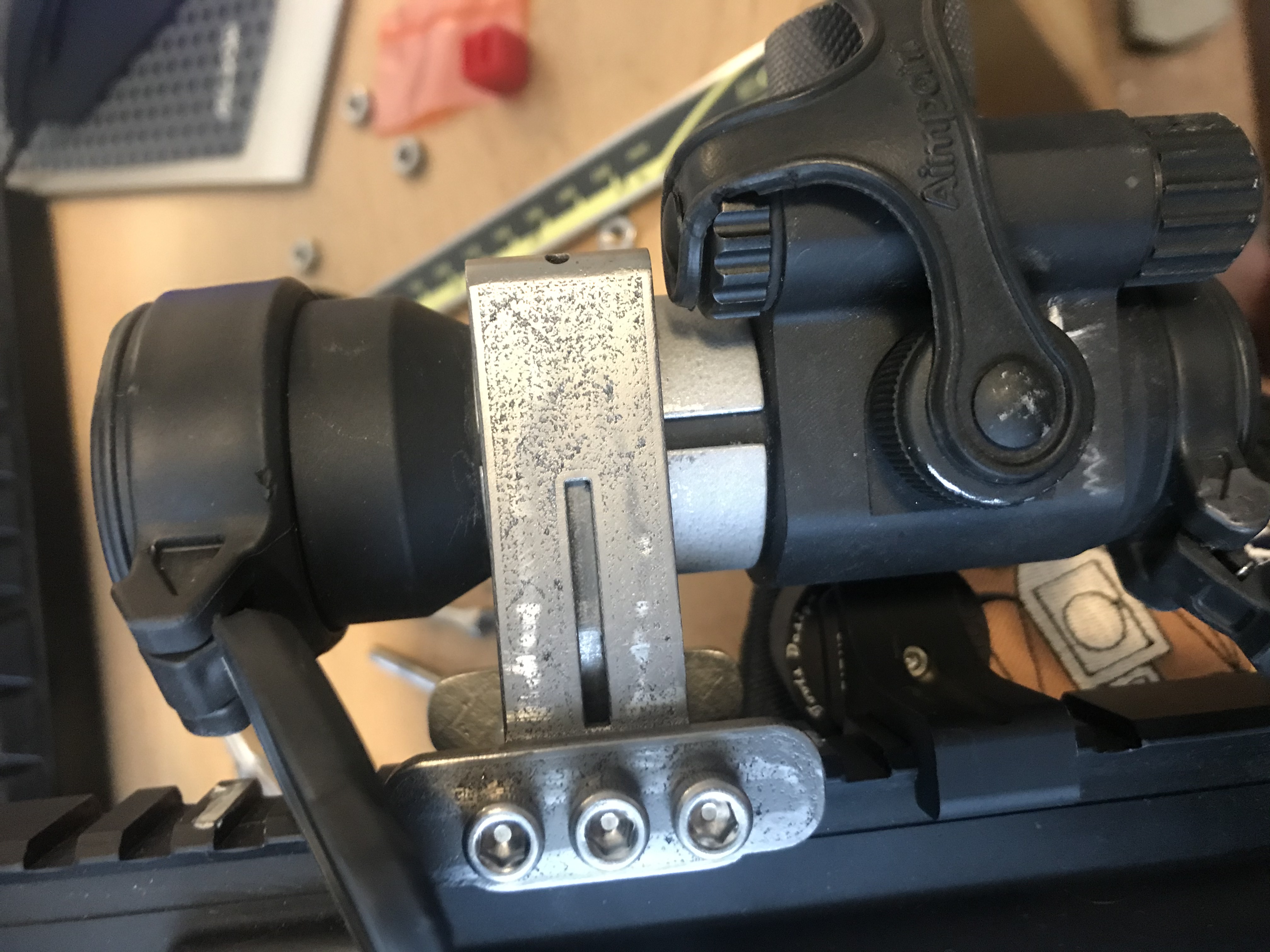
I have a long list of cheap mounts, and they always seem to fail at the threaded embossments into material not made for the job (6061AL). On the other hand, when you look at a Scalarworks or a Spuhr, either the material is sufficient to hold the thread, or in the case of Aimpoint there are Helicoils. The Scalarworks design has eliminated many failure points altogether, however their design is very weak around the top pin and mine broke! (At least the Aimpoint pro mount, my only experience with them.)
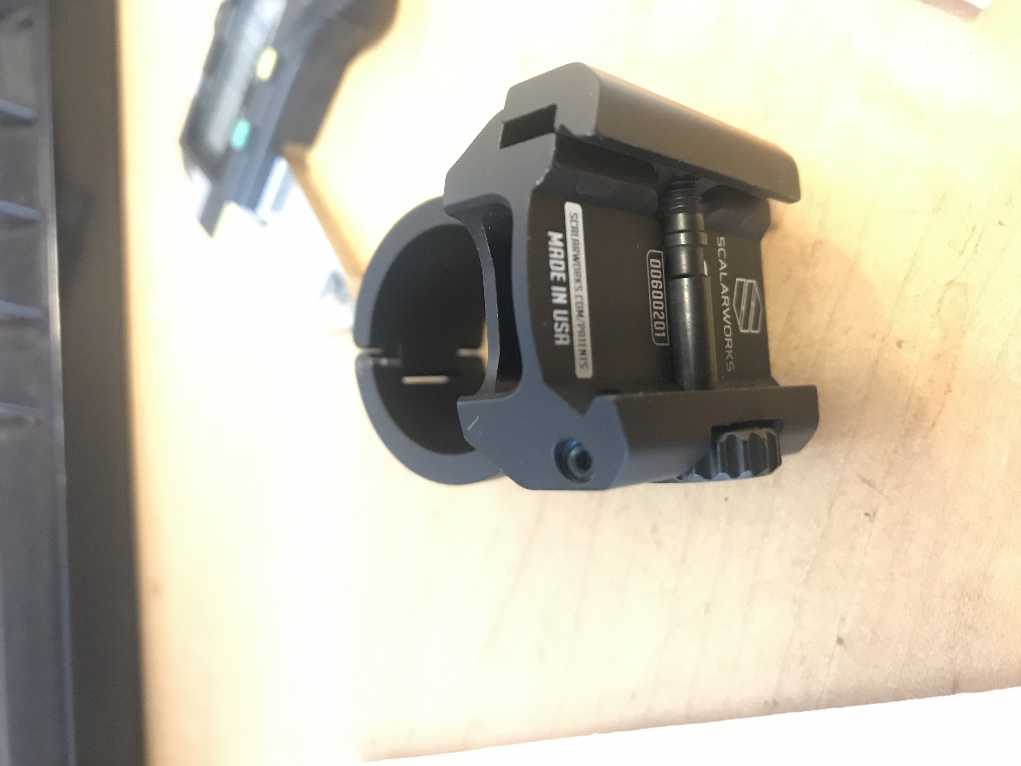
This is not to say anything bad about the Scalarworks mount. The Engineering, Tolerances, and Materials in that mount, make it probably the best strength to weight mount on the market. Further, their customer service is so great, that they sent me a new mount, faster than most companies ship a new purchase!
The images do not show the failure mode very well. The underside of the embossment has split. The top has just lost the anodization layer from the deformation of the underling material.
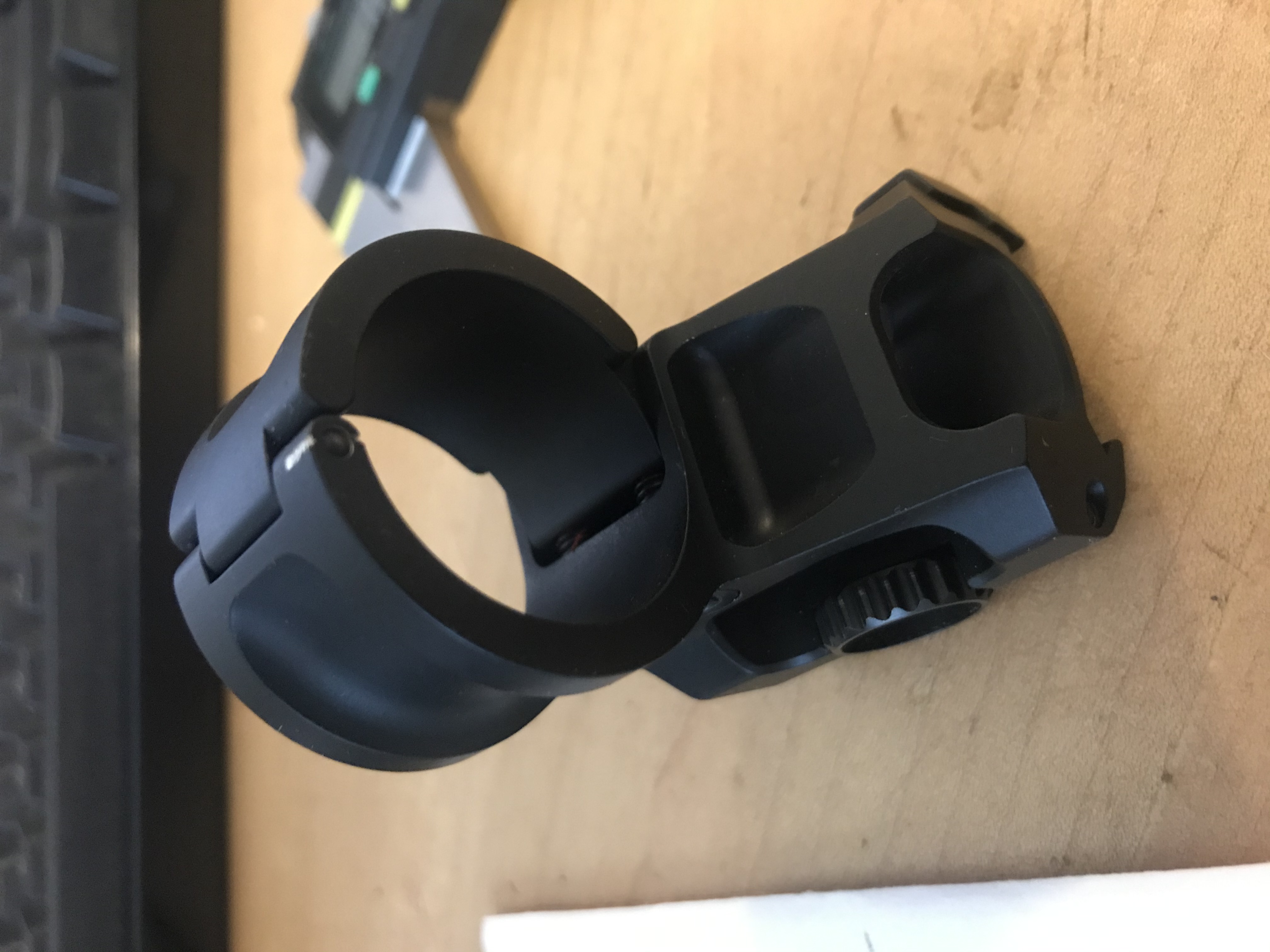
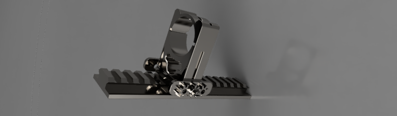
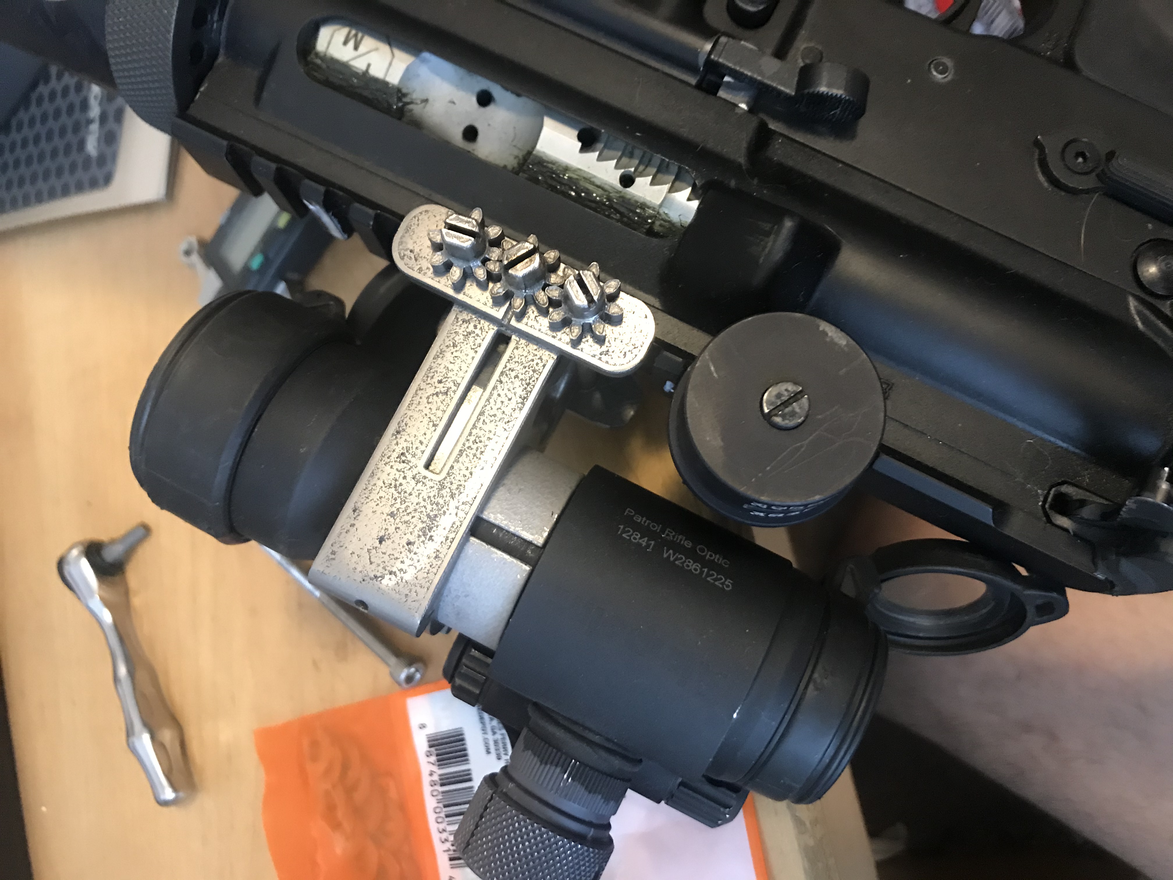
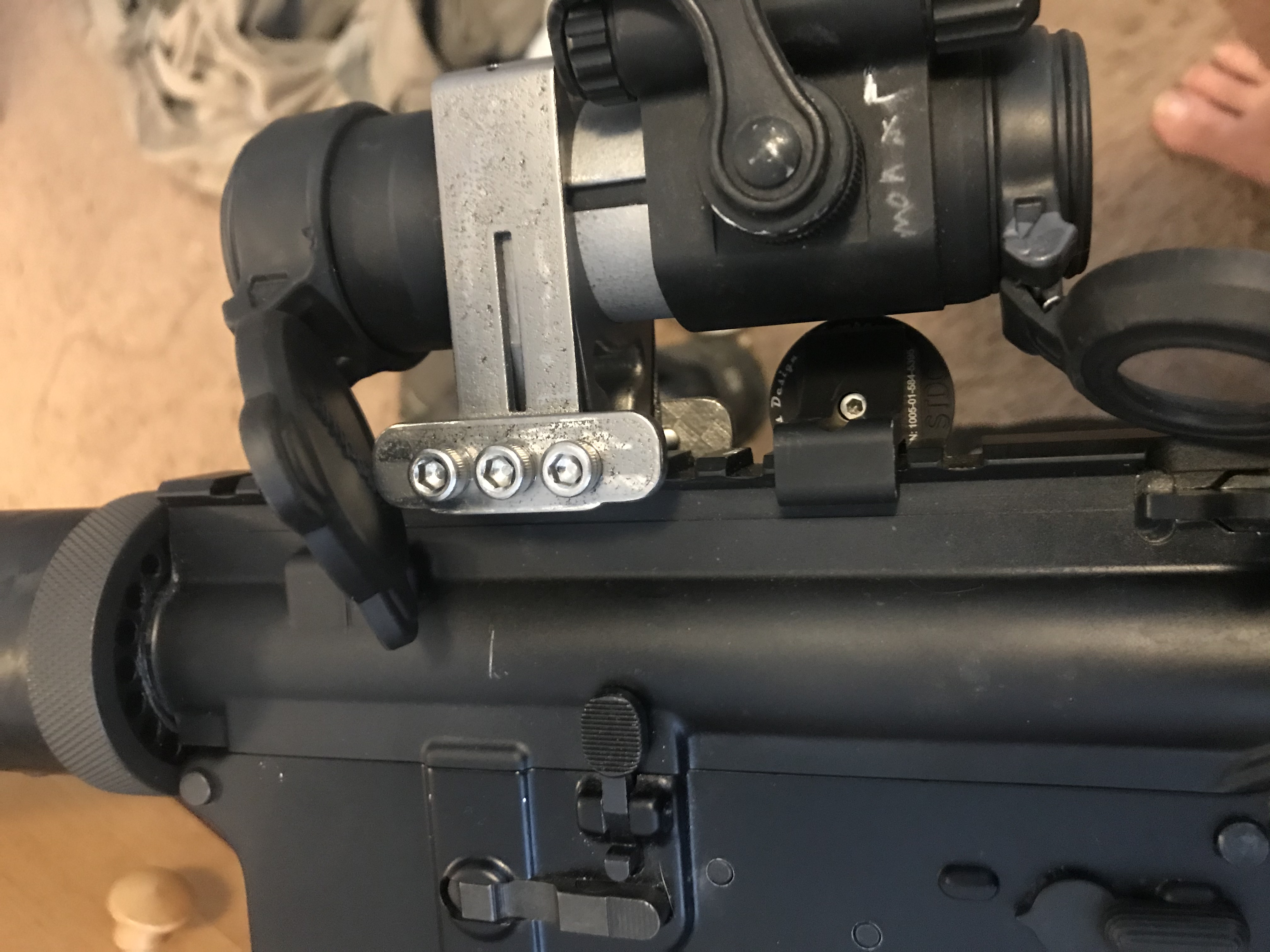
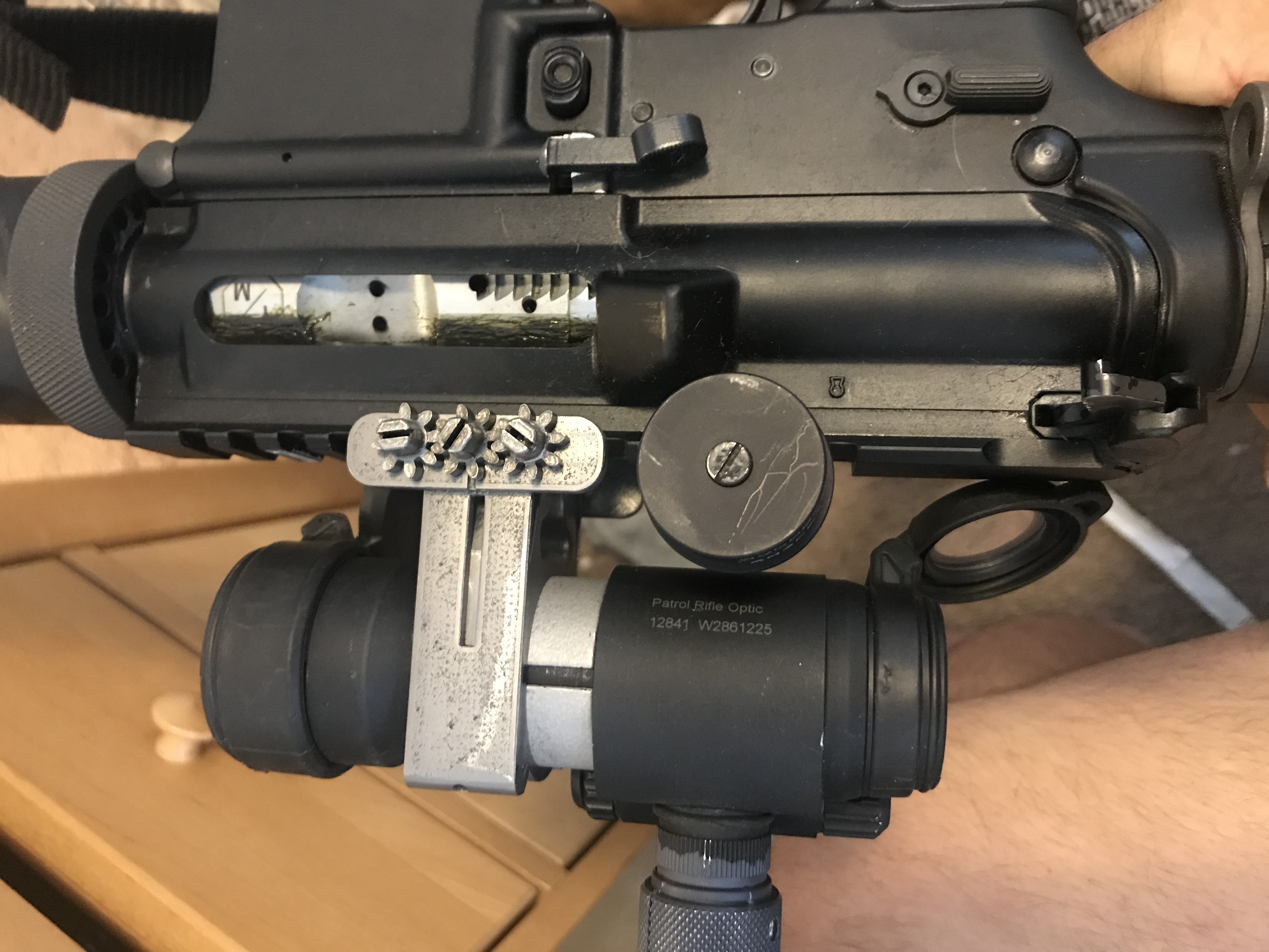
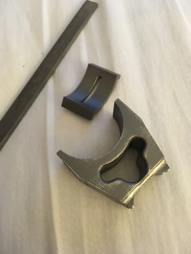
My design uses only 3 bolts that hold the responsibility of both holding the optic and grabbing the rail. The threads are going into Laser Sintered 6AL4V Ti, and the nuts are actually interfacing gears. This means if one is loosening, the others are tightening. By compressing the rail side of the mount, the rail is utilized to squeeze the mount to the optic as well. The other side of the bolts are safety-wired after installation.
Part of this design was that it was always going to be 3-d printed (laser sintered) Titanium. With this comes the benefits of such a process (such as infinite fillets and impossible to machine geometries, with no worry of a tool change). However there are also a set of maybe not so desirable qualities also accounted for. Though this is by far, the cheapest way to prototype, it is by far the most expensive way to produce. The process is not ”cheap”. Another (non- in my case) issue is that it comes close to billet, but is still a tiny bit less dense. The caveat that does affect me, is dimensioning the components to fit together. Where you can give a machinist a, say +.005” - .001” specification on one part and a + .004” – 0.00” tolerance on another interfacing piece, and get a maximum lash of .002”, the math gets much more complex with laser sintered metals. The geometry is what determines whether the process will print over, or under the blueprint. For instance, an inside corner with a lip, might sag .005” or a bur might develop on a blind cavity somewhere.
With this in mind, I engineered this mount system with features where material could always be taken away, or added to to allow the unit to fit together correctly. Further, the math is probably out there to figure out, with some degree of precision what the final part will look like to develop around. But I don't have that math, nor could I find it. So I drew the parts with zero tolerances and no lash. Since I was expecting to fit the parts by hand anyway, and I had no idea what would be too big or too small.

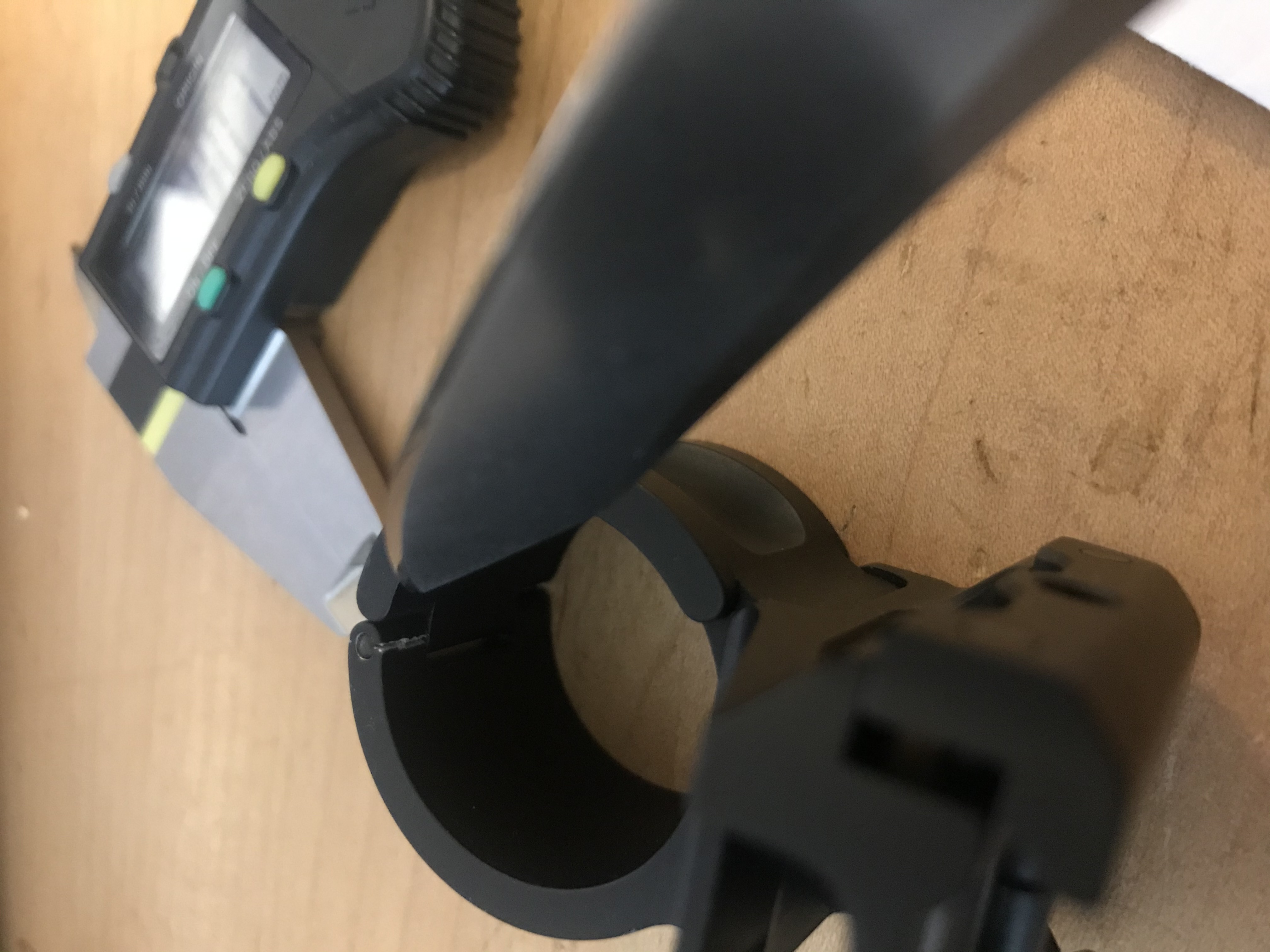
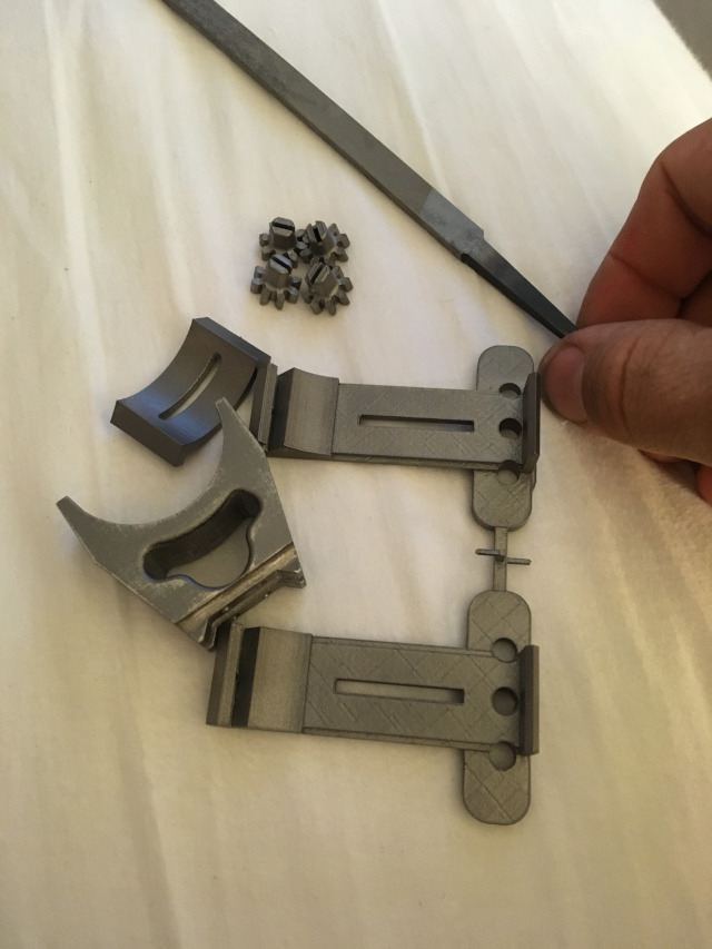
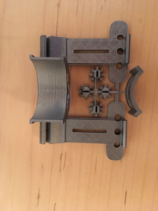
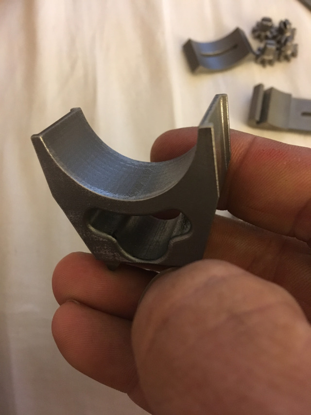
There are a few mechanisms built in to accommodate tolerancing; There are holes meant to be drilled and tapped to take up extra lash in the event the components in those specific critical dimensions where too loose, and there are Flats on areas where material can be removed for better fitment in the event that there is too much interference. As it turns out, nearly all the critical areas (actually most dimensions) came out larger rather than smaller. Tolerance stacking in some places with up to .0075” like where the Cap interfaces with the Bands at the top. This actually worked out quite well and along the way I got pretty good and fitting the parts.
Obviously, a metal file was my friend, but also a DMT diamond plate made it easy to keep things square and flat. When I started getting close to a good fit, I would switch to some valve lapping compound and seat the parts together. There was enough springiness in the material, that after the lapping compound was removed and the debris was cleaned from the parts, their fit was very smooth with next to no slop.
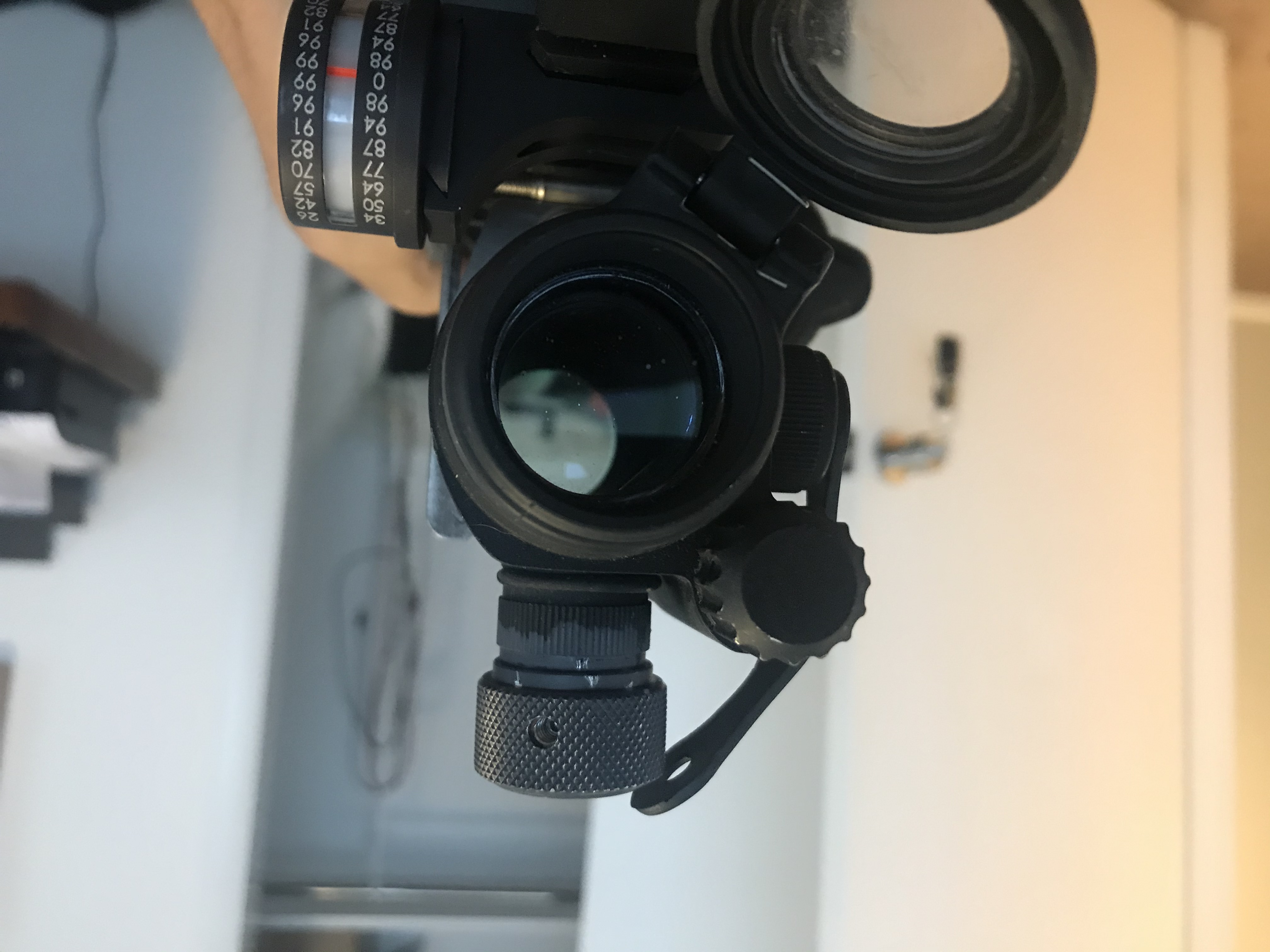
The mount was designed for 34mm tubes. I made a 30mm adapter for the AimPoint Pro. I had this printed in Aluminum. It's cheap, light, has a fair resistance to corrosion, and is softer than the mount and the optic.