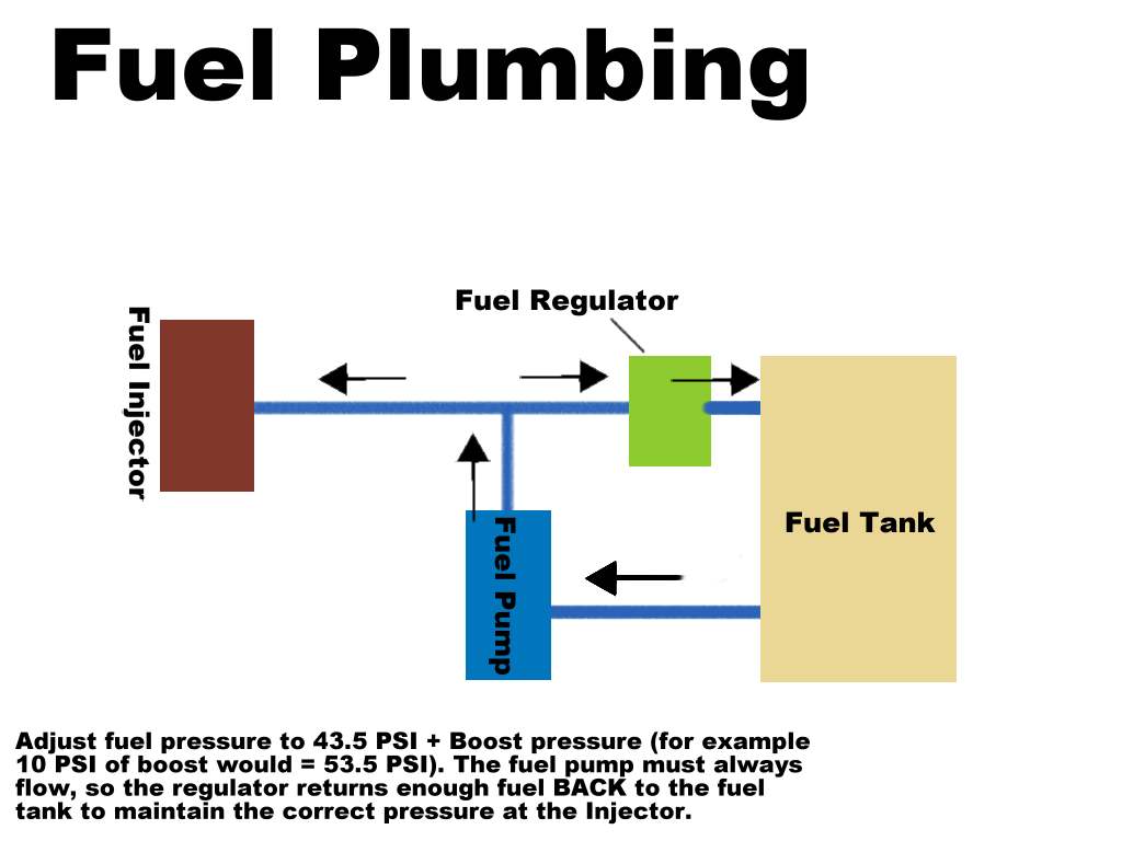
This gives an idea of how the regulator works as well. There is a spring-loaded diaphragm in this (cheapo off of eBay) fuel pressure regulator that compares the outside pressure and the spring loaded bias (that we can adjust to adjust the pressure) to the fuel pressure in the line. When the fuel pressure is over the amount we need, the diaphragm pushs open a valve and it allows fuel to flow BACK into the tank. This is important, and means that when the fuel pump is on, fuel is always flowing. ALWAYS, either into the fuel injectors, back to the tank, or both. It is as simple as that.
Now there is just one other issue. That is the issue of the actual ambient pressure that the regulator is comparing it's pressures to. In the fuel injection manifold there is a vacuum when the engine is pulling fresh air into the cylinder; to meter the correct amount of fuel (using duration of the fuel injector being opened, to control how much fuel we put into each cylinder) there needs to be a constant pressure of fuel, regardless of the amount of vacuum in the manifold. To correctly regulate this, we connect our regulator's ambient pressure port to the fuel injection manifold directly. Therefor when pressure is added to, or subtracted from (14.1-14.7 PSI, or 1 ATM) the manifold, the regulator can compensate with more or less pressure in the fuel line.
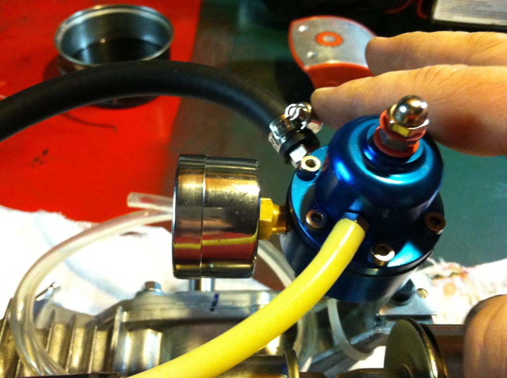
Image of surgical tubing coming from the ambient pressure port of the fuel pressure regulator.
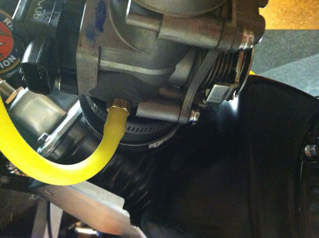
Image of pressure reference port I installed on the Honda 250r fuel injection throttle body.
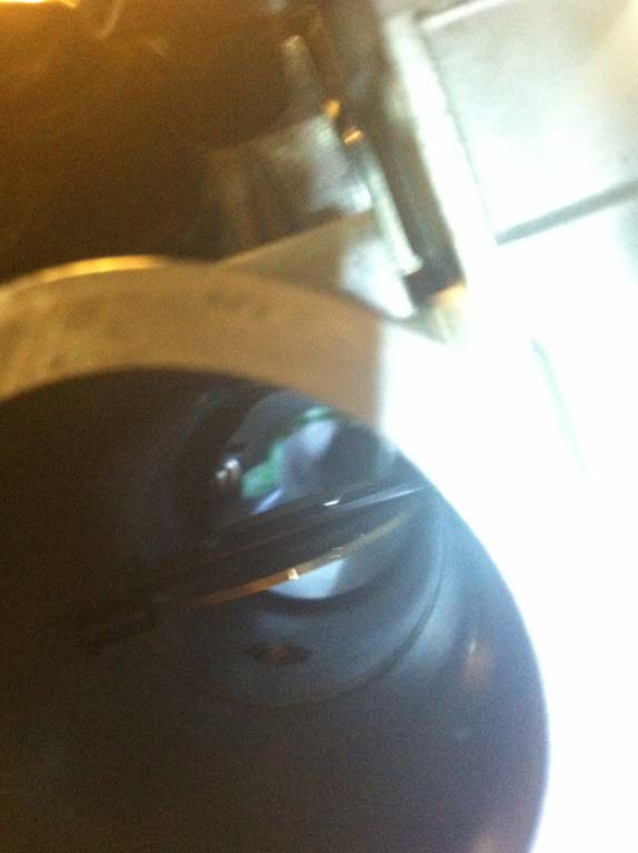
This image shows that I installed the pressure reference BETWEEN the butterfly valve and the engine, not before.
In a normally aspirated engine, when the throttle is closed, obviously there will be an increase in partial vacuum (a decrease in pressure) in the manifold between the butterfly valve and the cylinder. This means you will want the regulator to compensate by OPENING and allowing more fuel to bypass back into the tank.
With a turbo engine, the concept is the same, when the manifold transitions from vacuum to boost, you will want the regulator to compensate by partially CLOSING and not allowing as much fuel to return to the tank, thereby maintaining the intended pressure.
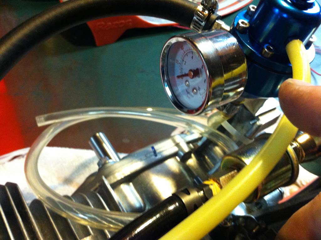
This is a picture of the fuel pressure regulator with gauge, mounted on the engine. This is a Chinese one, about 30 bucks before shipping.
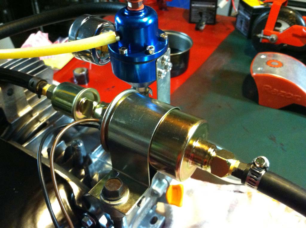
This is a picture of the fuel pressure regulator with the wrong fuel pump installed.
I actually purchased the wrong fuel pump, the one in the pictures is not what you (or I) need. The trend for Fuel Injected vehicles is to have the fuel pump WITHIN the fuel tank. This is not what I wanted because I am making this thing up as I go, and it's a good idea to keep all of my components as modular as possible. Most external fuel pumps are for carbureted vehicles and they only require enough pressure to fill the bowl of the carburetor. That is about 1 or 2 psi. I need 43.5 psi + whatever my boost will be so the one I purchased (a low pressure external pump) will not do.
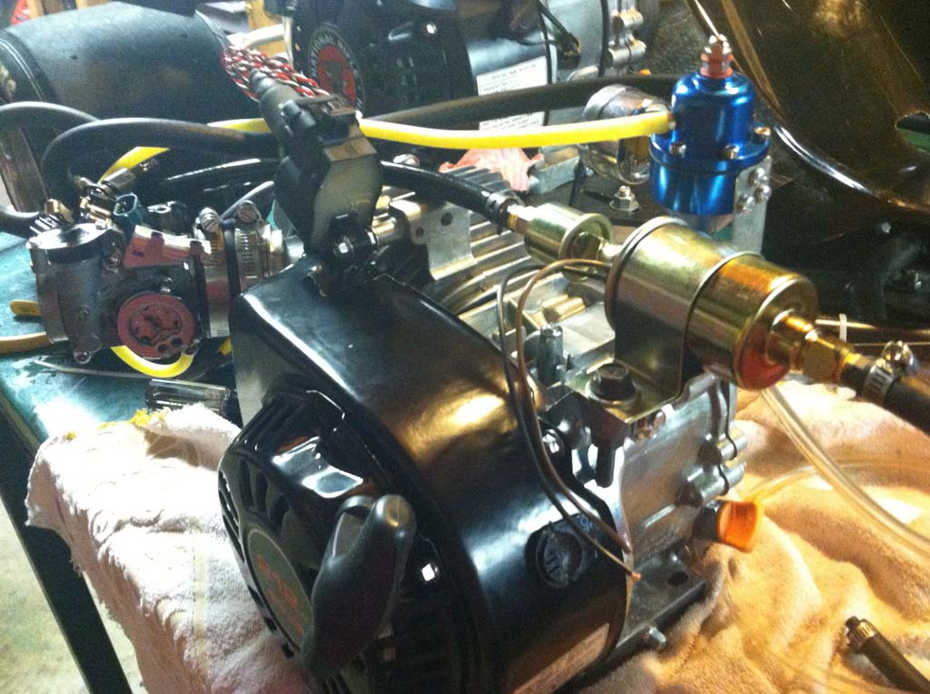
Here is an image of the wrong (low-pressure) fuel pump I installed. I will install a correct high-pressure one here later.
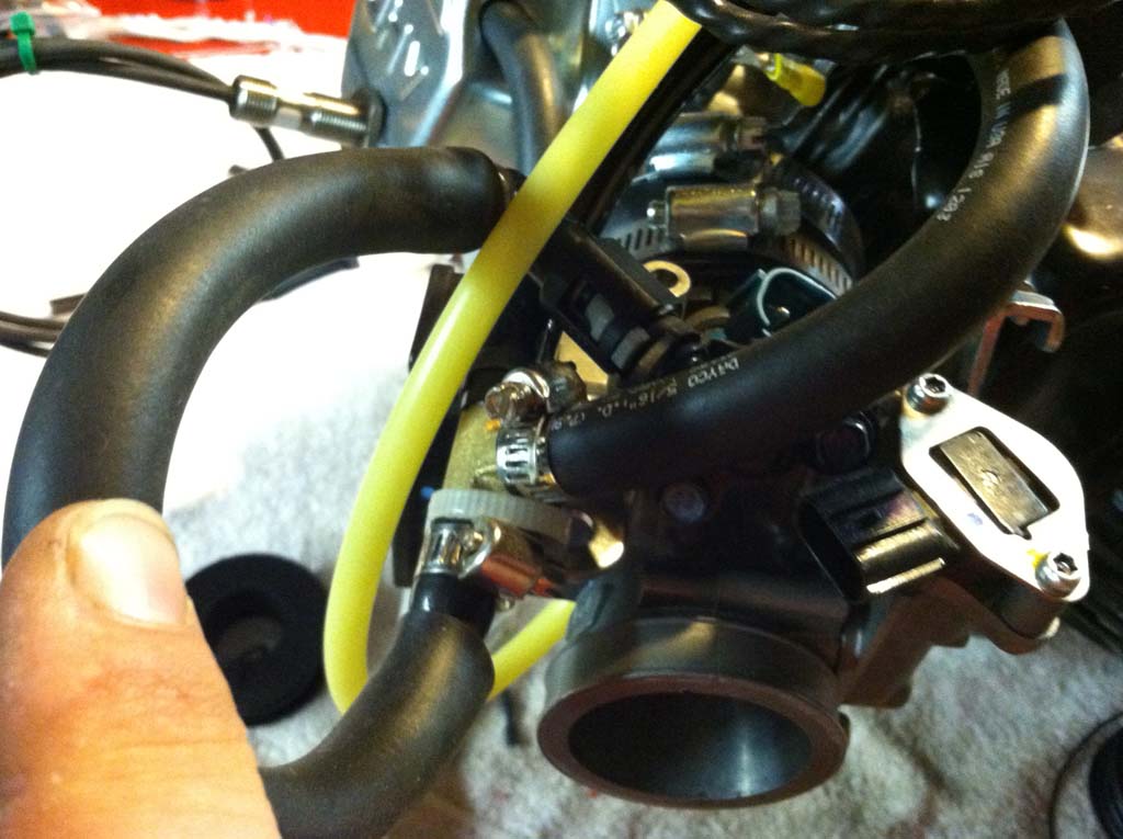
This is an image of the brass 'T' barbed junction that splits the fuel line coming from the fuel pump. One side goes to the fuel injector, the other side goes to the regulator.
The problem with external fuel pumps that are made for fuel injection systems is that since they are not OEM in-the-tank replacements, they are typically for racing applications and that means they are EXPENSIVE! Flow rate is not really going to be a problem for me since I am only feeding a 200cc single cylinder at around 7000 rpm however, the pressure needs to be at least 55 psi, that gives me a good cushion at the top end. My buddy put me on to this one:
        Jeg's  Hi-Pressure Inline Fuel Pump
        255 LPH
        Approx. 5" Long x 2-1/2" Dia.
        Inline Fuel Pumps
        Item# 555-159001
        www.jegs.com
The above pump is $132.99 but they can go to half a grand. Of course, if I do decide to find some type of in-tank option, you can find those on eBay for around 50 bucks.
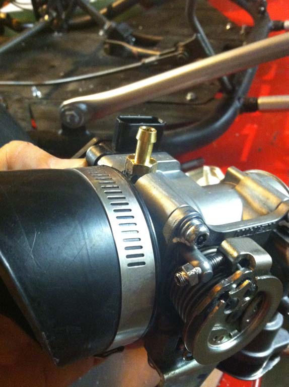
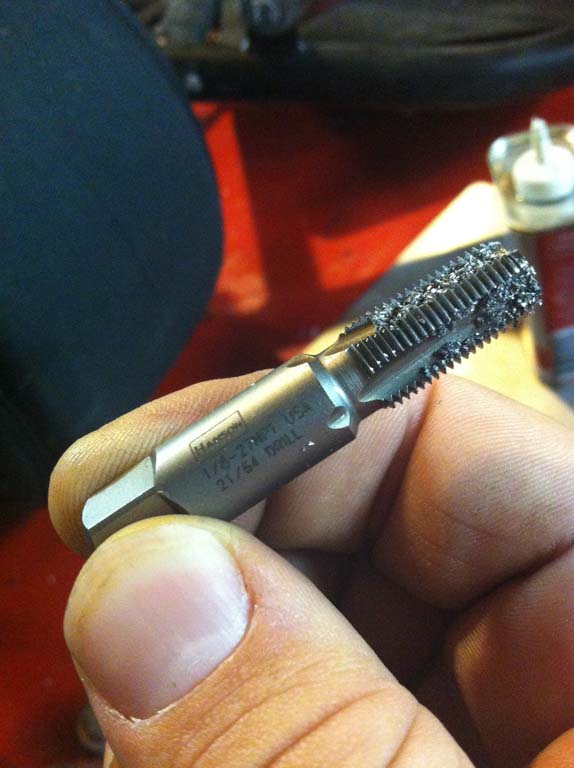
This is an image of the throttle body with the hose barb fitting installed. I used a 1.8 27NPT Hanson tap to thread the hole, and a 21.64th drill to make the hole. I used an auto punch to scribe where I wanted the hold and then used a small drill to create a pilot hole first. This was because the large hole had to cut through materials of different heights. This would have been very hard to drill without a drill press. The material was a little thin in one place, so I used some epoxy putty to reinforce the install. It probably didn't need it, but I would rather it work good over look good.
Much of this information I received from MacsBoost and MegaSquirt Fuel Injection
For the electronic ignition I have installed an LS1 coil because it really takes care of all the heavy lifting your electronics would otherwise have to do. You give the LS1 coil 12 volts and it uses a 5 volt trigger signal to fire the coil. It's that easy and will connect directly to your Mega/MicroSquirt.
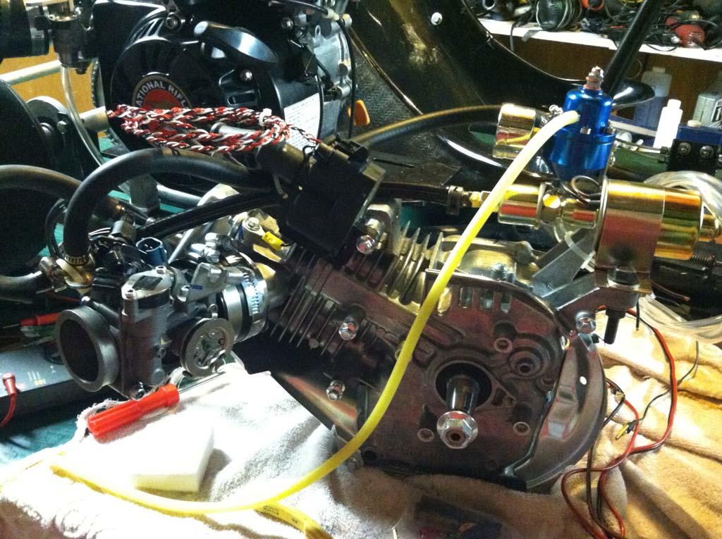
Here is the LS1 Ignition coil (a Chinese module) D580, The non-OEM modules are around 22 bucks.
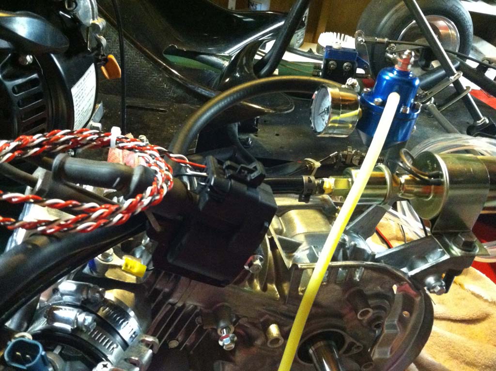
From back to front: 12 volt Positive, 5 Volt Signal, Chassis Ground, and Ground to Battery. Here is a good link for wiring information: LS1 Coil Wiring MiataTurbo.net
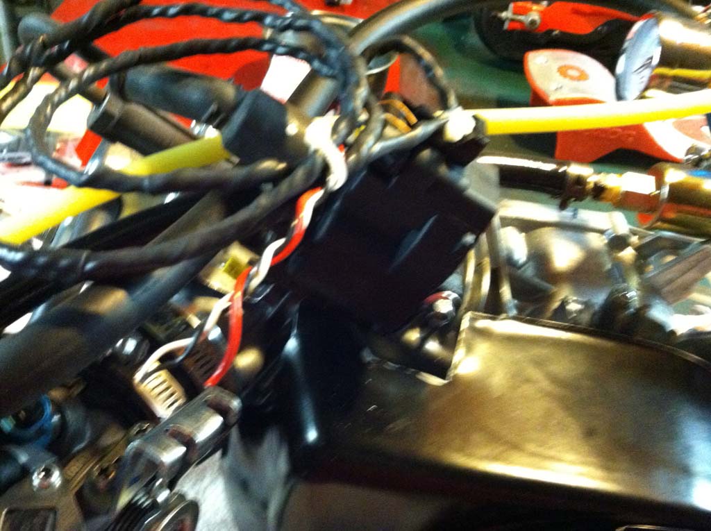
I tied the wires and through some heat-shrink over them. I also tied the connector to the wires to aid in strain-relief.