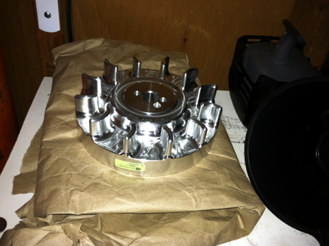
This is the flywheel I purchased from ARC, these are great people. I needed a flywheel with no magnet, or magnet pocket milled into it. My thought is, I will take a balanced flywheel and thread holes every 10 degrees that I will place screws in. I will then place a hall effect sensor where the magneto was, this will give me an RPM measurement when I connect the Mega-squirt! What about spark you ask? Well the Mega-squirt will take care of the spark timing and the charge will come from a 12 volt battery. I am very lucky to be around knowledgeable people in this arena, Mac of MacsBoost.com for example, suggested using an LS-1 coil, this assembly gets fed 12 volts and then when it's 5 volt line is pulled it produces a spark. Easy!(maybe) I called ARC to see if they could make me a special flywheel They did not mill the holes I needed, but they did leave out the g-code for milling the magnet pocket, for the same price as their stock flywheel, so I couldn't be happier. It is a real piece of art too.
I actually have two of these predator engines now, this one I cut the oil sending wire off art the connector and pulled it through the sealing cable-gland. Then I took the cable-gland out and cleaned it, then I pushed RTV through the center of it until it came through the other side. I think this is a better way to seal the hole, and I think it looks a little better too.
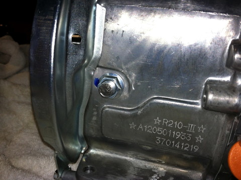
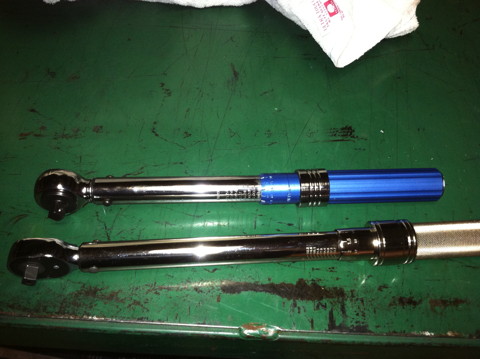
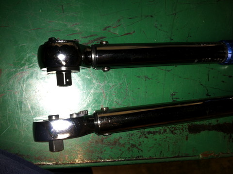
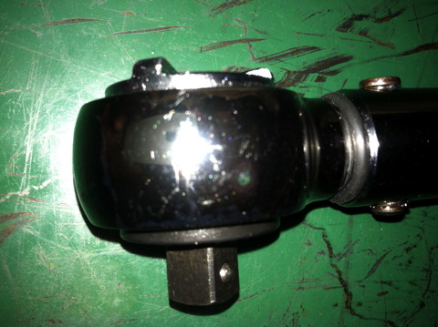
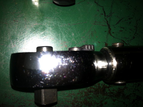
One thing I would like to add about the rod install; the torque wrench you use should be thought about. I mean it needs to be accurate and all that, but also, I ended up using a ft/lbs wrench on an inch/pound part (same amount of torque, just divided the units by 12) because the head of my inch/pound wrench would not fit where my foot/pound wrench would! The pic of the smaller headed FOOT/lbs. wrench is the last one on the right.
The motor so far
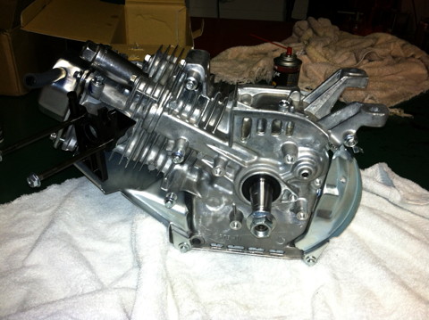
Phase 2!!!
This time around I needed to install a sensor to acquire cam position. You could theoretically do this with a speed (RPM) sensor on the flywheel, but you would never know which cycle you were in. (because the cam is geared 2:1) This means you would have to fire the spark not only in the transition from the compression cycle to the ignition cycle, but also at the transition of the exhaust cycle to the intake cycle, because you would never know which revolution (of the 2 revolutions that complete the 4 strokes, in a 4 cycle) you were in. This method would work just fine in a normally aspirated engine. In fact these little 4-strokes all work that way out of the box (the ignition fires every cycle of the flywheel) but since I plan to turbo charge this motor, we will want finer control of the spark, and we will also want to more accurately time when the fuel is injected. Thus we are adding a cam position sensor! I will also install the actual fuel injector. The fuel injector comes from a Honda CBR 250R motorbike. This really makes it easy because the throttle body is where the injection takes place, so I will just install the entire throttle body and with it, I will get the fuel injector, a throttle position sensor, and an air sensor.
Before I start all this work, I Decided on a bit heavier valve springs, this ones I purchased are shady but the salesman told me they were 22 pound springs; we'll see. To put them in, I do not want to have to remove the head again. To do this I will set the piston to the bottom of it's stroke (use a chop stick in the spark plug hole to find bottom dead center) then take the valves off of their rockers.
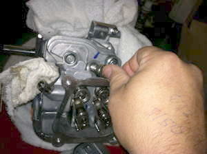
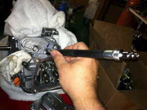
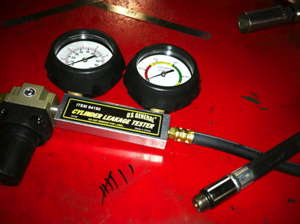
The trick here is to use compressed air inside the cylinder to keep the valves pressed against the top of the head while you work on the engine. That's why it is important to take the valves of the rockers FIRST. Otherwise you take the risk of creating a compressed-air powered motor, at very least for a revolution or two. I found the standard air fitting on a leakdown tester I had, if you don't know what I leakdown tester is, look it up on youtube, it is a very useful tool. This fitting I connected directly to my air compressor, it didn't take much air, maybe 30 psi.?
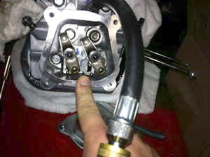
After the springs were installed, and the valve lash was set back to .002" I went to work on the cam position sensor. I could have done this in a thousand different ways. One way being to install a sensor in the crank case to directly monitor the cam. I chose instead to mount the sensor on the valve cover directly above the intake push-rod. I did this so when I blow up a motor, I can simply install this valve-cover sensor assembly onto the new motor. I opted to use a hall effect sensor: The Cherry GS100102 Gear Tooth Speed Sensor, to be exact. This is a stainless steel bodied, fully threaded, bolt-like sensor that can easily be mounted with just a hole. There are probably better, and cheaper solutions, but this is what I ended up with. I believe it was around 44 bucks from Allied Electronics.
Other factors that cam into play choosing this sensor were it's heat tolerance, this sensor works to 125C, it's wide input voltage 5-24v DC, and it operates at a high frequency. The data sheet does not give it's frequency, but instead gives reaction times for the internal transistor's rise and fall times. I may be wrong about this but I have been calculating the sensor's suitability like this: 5uS it fully sink, and 5uS to fully recover. A microsecond (uS) is 1/1,000,000 of a second, or 1*10^6 Hertz (1MHz) if that were the time per cycle. Thus the theoretical frequency limit for this sensor is: 5uS sink + 5uS recover = 10uS for a full cycle. 1,000,000(uS) / 10uS = 100,000 cycles per second, or a 100KHz possible switching speed. this number seems incredible high to me, and most sensors are rated at a maximum of 20KHz, but we aren't getting anywhere close to that number. Let's say the maximum planned RPM of this motor is 10K. The cam is geared down 1:2 so this takes our number down to 5,000 Rpm, since we only need to know when the intake cam is fully opened, we only need one actuator for the sensor. That's only a maximum of 5,000 cycles per MINUTE, we could at very least to 20,000 per SECOND. So the speed of the sensor will not be a problem either. It has a maximum output current of 20mA. This is more than enough for the Mega-squirt. There are three wires on the sensor: VCC (+5 to 24 volts DC), Ground, and Signal. To give the sensor wire power, you connect a current limiting resistor from VCC to the Sensor lead. When no Ferrous metal is near the sensor, the sensor will read "high", when metal is near the sensor, it's internal transistor will pull the sensor wire to ground and the sensor lead will read "low". It's that easy.
The maximum current for this sensor is .020 A (20mA) but it does not take near this amount of current for most logic devices to read the status, in fact with these
current levels you could drive an LED! The Data sheet recommends operating the sensor with a 5mA signal. This is easy to obtain with Ohm's law (E over I and R)
(Voltage over Current and Resistance) at 5 volts / .005 amps you need a 1K Ohm resistor to get a 5mA signal. At a 12 Volt operating voltage (like a car battery that
I will be using) 12 volts / .005 amps = a 2.4K resistor.
Gear Tooth Speed Sensor Specs Link
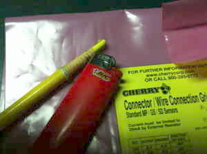
I could have spent all day finding obscure ways to measure where I needed to drill the hole in the valve cover to place the sensor exactly over the back end of the intake rocker (right over the push rod), but I came up with a better way. I melted a piece of a China grease-marker and stuck it exactly in the center of where I wanted the sensor to be on the rocker, then I installed the valve cover. When I removed the valve cover, I had a mark exactly where I wanted to machine my hole, it worked great.
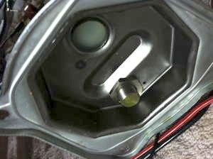
I used some Dychem to mark the sensor face, and glued a few shims to the rocker temporarily to set the clearance of the sensor. This may be a issue later when the engine heats up and the RPMs get high, we'll see.
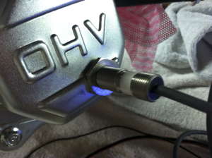
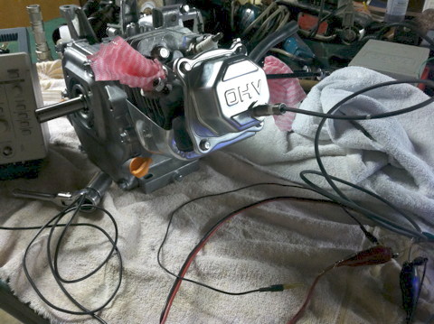
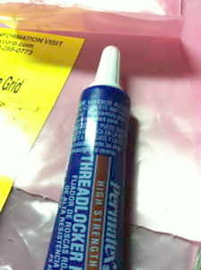
I used red Loctite on the sensor nuts, especially because there is s nut inside the valve cover, I do not what to set my self up for catastrophic head failure. I tested the sensor with a little oscilloscope and a drill on the crank.
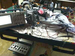
On to the fuel injecting throttle body. Part of modifying a clone motor for use with a kart is removing the stock airbox and installing an "airbox delete" adapter that will except a cone "K&N" type air filter. This adapter was a perfect diameter to use with the spigot adapter on the CBR 250R throttle body. The only issue was that the carburetor needed to be removed, and the studs were not fully threaded.
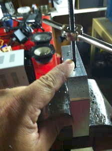
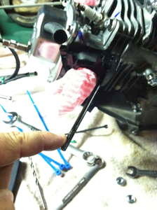
Threading the studs was no problem. To take the studs out of the case, I tightened 2 nuts against each other until they were tight enough that I could unscrew the stud. Then I drilled and tapped a block of Aluminum to thread the other end on of the stud into so I did not mar any of the threads on the other side of the stop (the stud flairs about half an inch from the case side to prevent the stud from going too far into the case). I threaded to the flair on the other side.
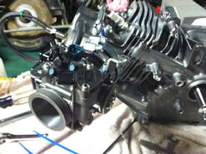
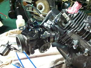
I used a small amount of blue Loctite on the case side of the studs, I probably shouldn't have, will see if it becomes a problem. I used the rubber from one of the cone filters to connect the adapter to the throttle body with two hose clamps.
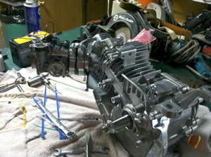
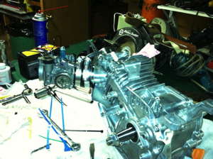
This is where I'm at so far!
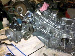
Turbo Predator Table of Contents