There is no doubt that the Microsquirt fuel injection approach is the way to go if you want the nicest, most tunable, 89 dollar turbo engine out there. However, as I kept dumping money, time, and ideas into this system, it became more apparent that I would need to be a fuel injection expert just to get this thing started. I enlisted friends and family to help to no avail, and while someday I might know everything there is to know about FI, today is not that day. It was time for a gross reappraisal of my approach. I decided to go the Carburetion route. The MicroSquirt is very doable, but my goal is a turbo Predator engine, and at this point, the quickest way to my goal is to carburate. The Microsquirt is on the shelf for now. You can expect better pictures (relatively) also; I have tried to stay under a certain storage limit for a long time for brainlubeonline.com but I'm at my storage limit so time for an upgrade, higher res pics to come!
There are many reasons for this major switch, one of them being that the math for the MicroSquirt, such as injector timing and duration is hard to compute, when you have absolutely no idea where to start. Further, cam timing on a single cylinder with the software I have seems ineffective. I have been told, that the non-free stuff can fix the problems I've been running into. At this point though, I just need to get this thing running because projects that sit unfinished, run a high risk of failure, and I've simply put too much time and money into this to fail.
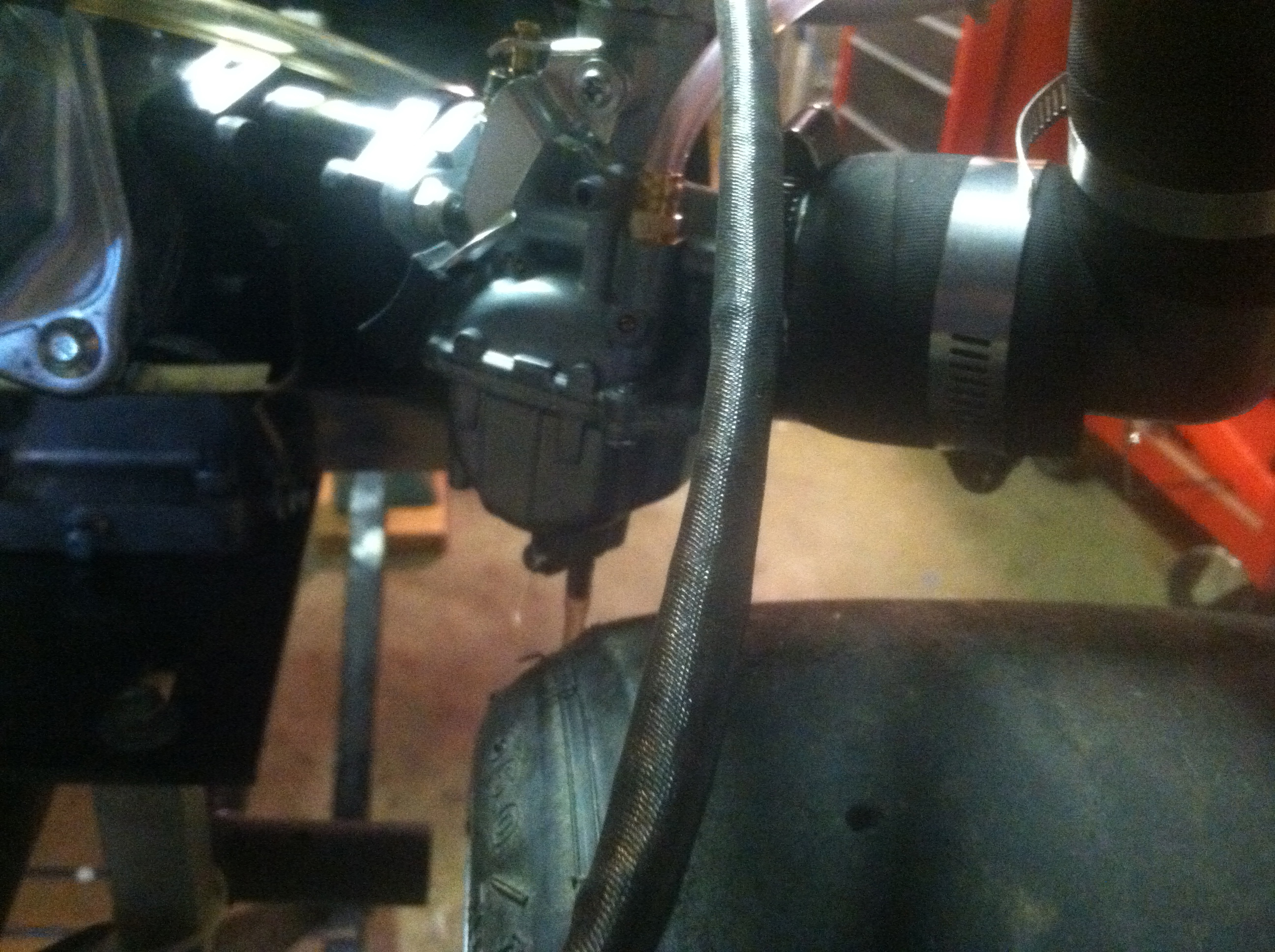
There are really two main types of Turbo/Carburetor configurations. The first being Pull-Through. This is where the turbo is closest to the engine and is pulling the air/fuel mixture from the carburetor. The second being that turbo forced air is pushing into the carburetor thereby into the engine. The pull-through method is the simplest and push through is a higher performer (generalities at a maximum). For this build I have elected to go with the second configuration, where the turbo charged, forced air is blown through the carburetor and into the engine.
There was a major paradigm shift in my thinking that had to occur to understand how a carburetor (That I have historically understood to operate on vacuum), can work under pressure. The fact is, carburetors operate in a pressurized environment already, (the earth at standard temperature at sea level being around 14.5 psi) it is the difference in pressure from one side of the carburetor to the other that causes the fuel to be mixed and atomized in the now fuel/air charge.
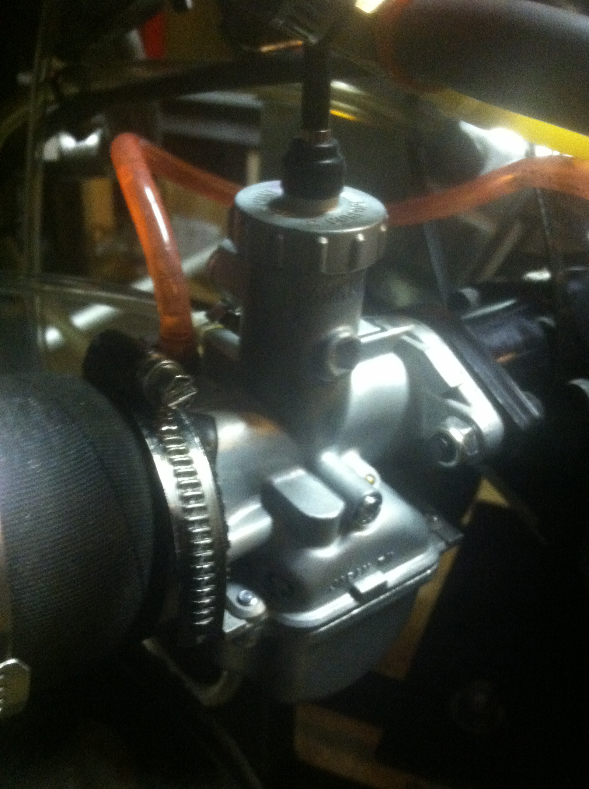
As it turns out, there are a few caveats. My fuel pressure needed to be set back to around 5 PSI over boost. Thus, I have a majorly TOO LARGE fuel pump now, but I'm not spending any more cash for the proof of concept so it stays, dialed way back. The fuel pressure is still regulated relative to boost, so it is still receiving pressure sign from the intake post turbo compressor. The Mikuni VM carburetor also has vent ports that the carb uses to relate intake pressures to ambient pressures. These (2 vents in the case of the Mikuni 22mm VM series) ports are now wired to boost sign as well since we are creating our own, higher ambient atmosphere. This is an important configuration and the engine will not even start without it,even when the turbo is creating vacuum instead of boost. Without equalization in the bowl, the boost can prevent fuel from entering the bowl. Too much fuel pressure and the float valve will be forced open (thus the fuel pressure is actively regulated).
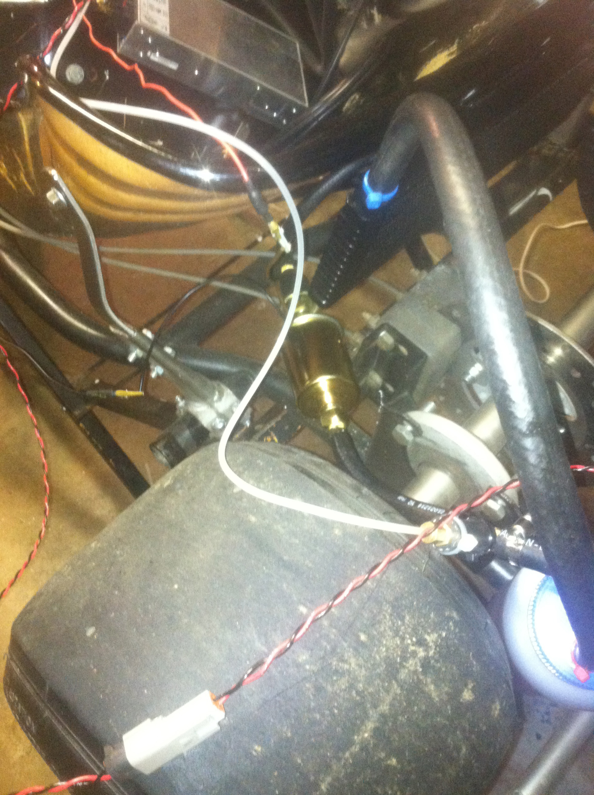
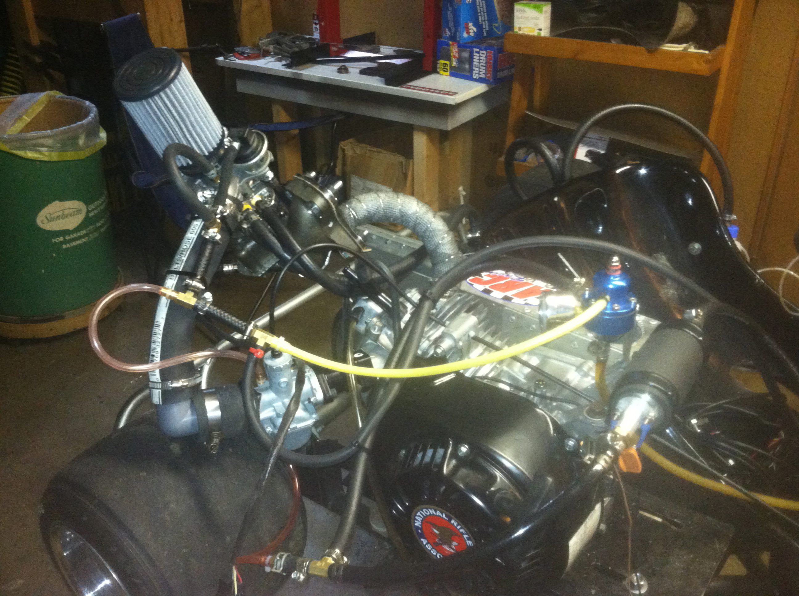
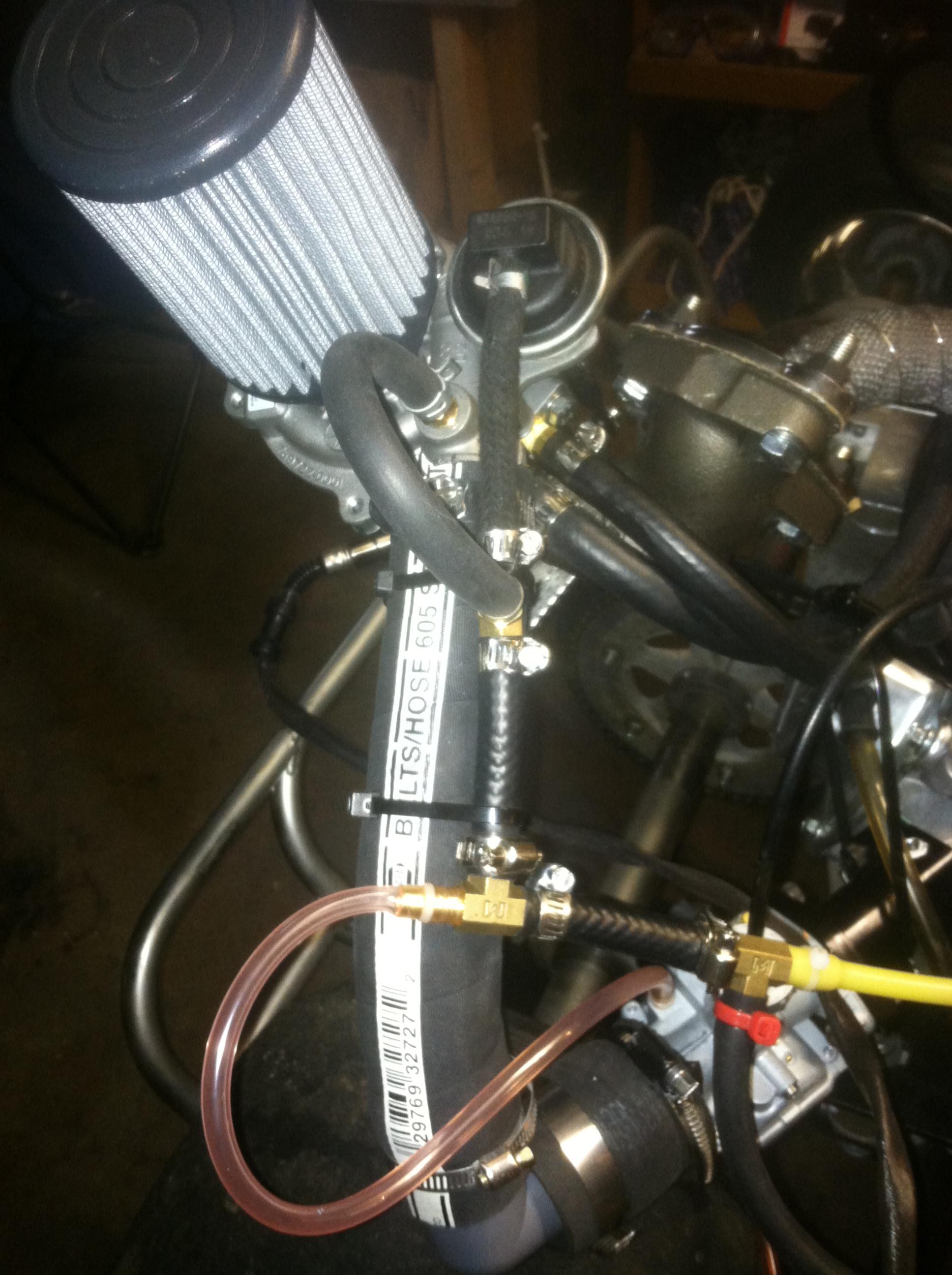
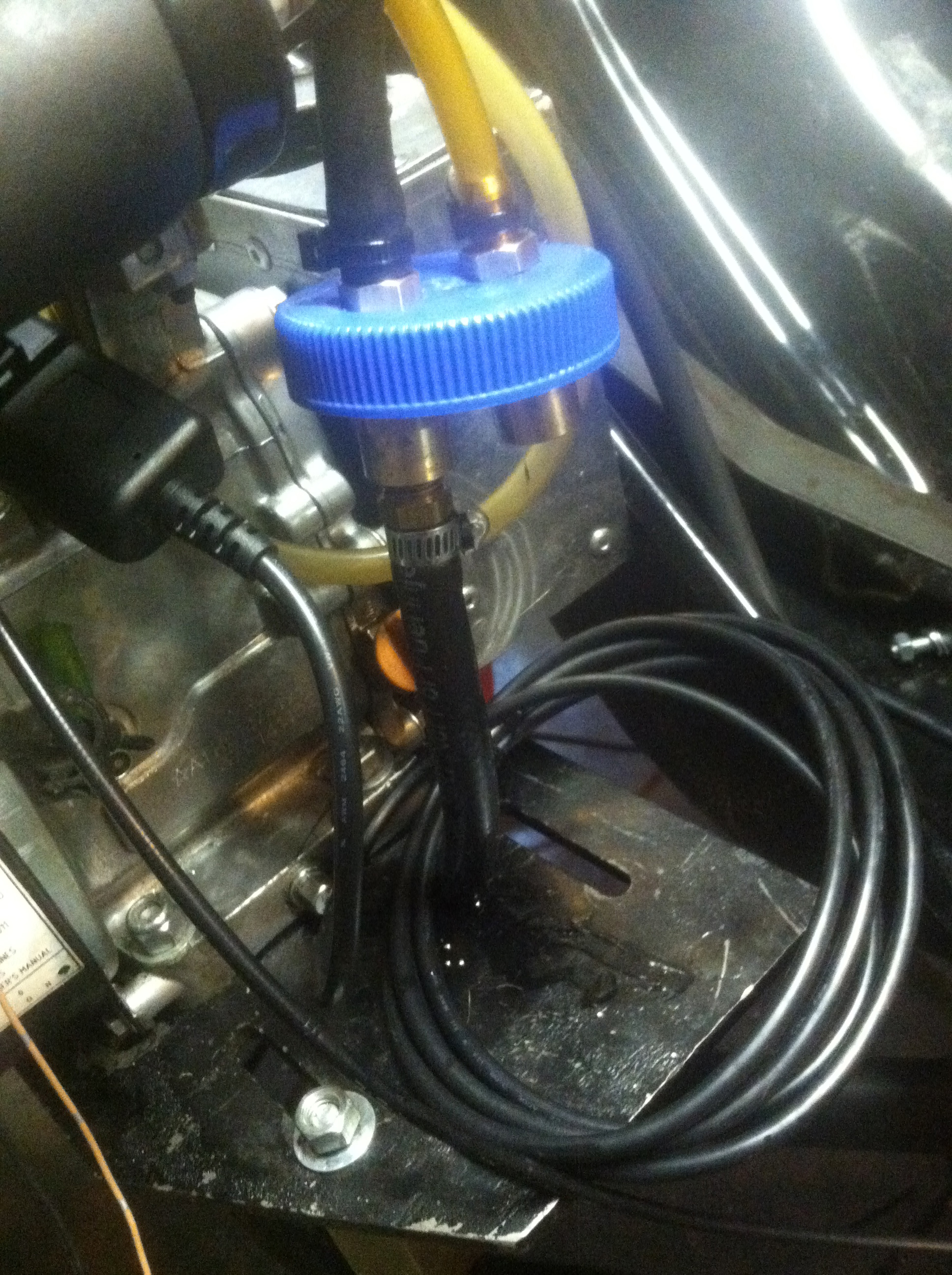
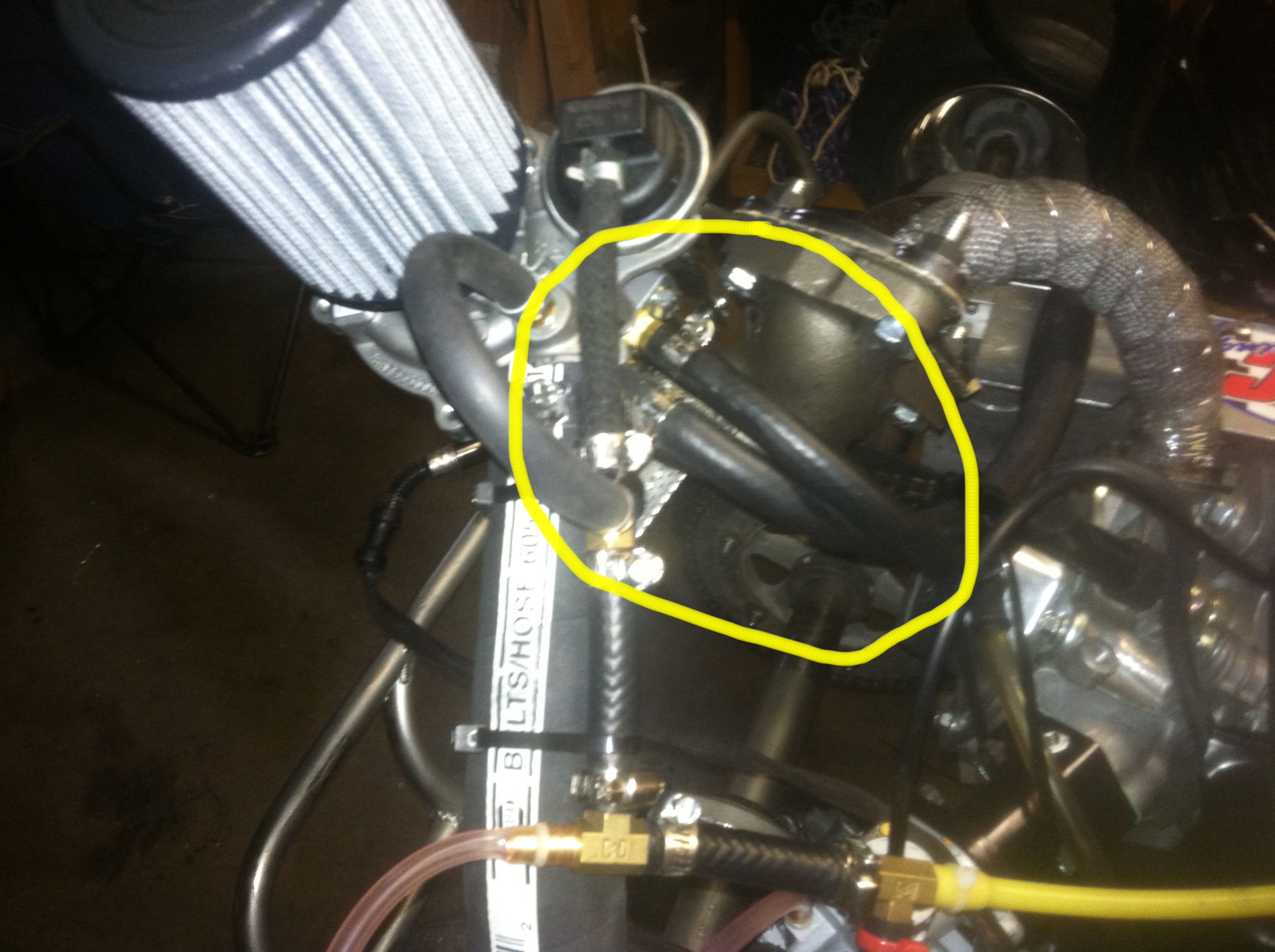
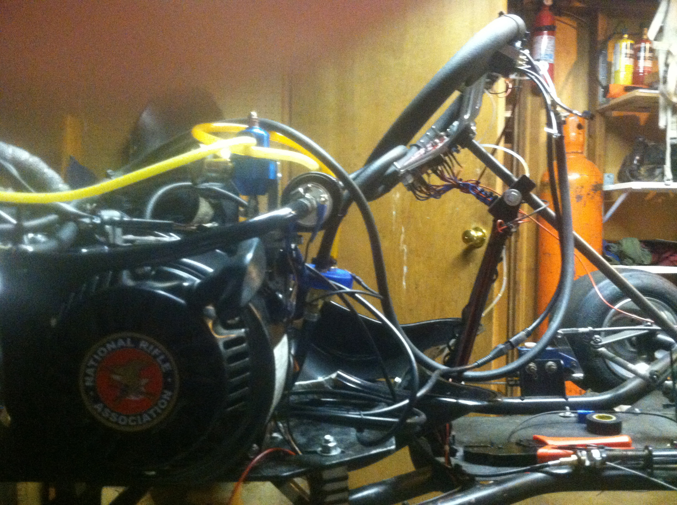
The images below show where on the turbo the boost sign is tapped. The turbo comes with a barbed fitting to connect directly to the bypass valve. I replaced that with a larger barb (of the same thread) and split it to route it to the two pressure ports of the carburetor, the boost gauge, the fuel pressure regulator, and the waste-gate (turbine bypass).
Note: I know it's messy. Wires and hoses could be routed with less fittings and less hose and less wire, in a much more organized fashion. This was made ad-hoc and is easiest to test, tune, add, and change. If I decide to keep the kart I will clean it up and add in some more safety.
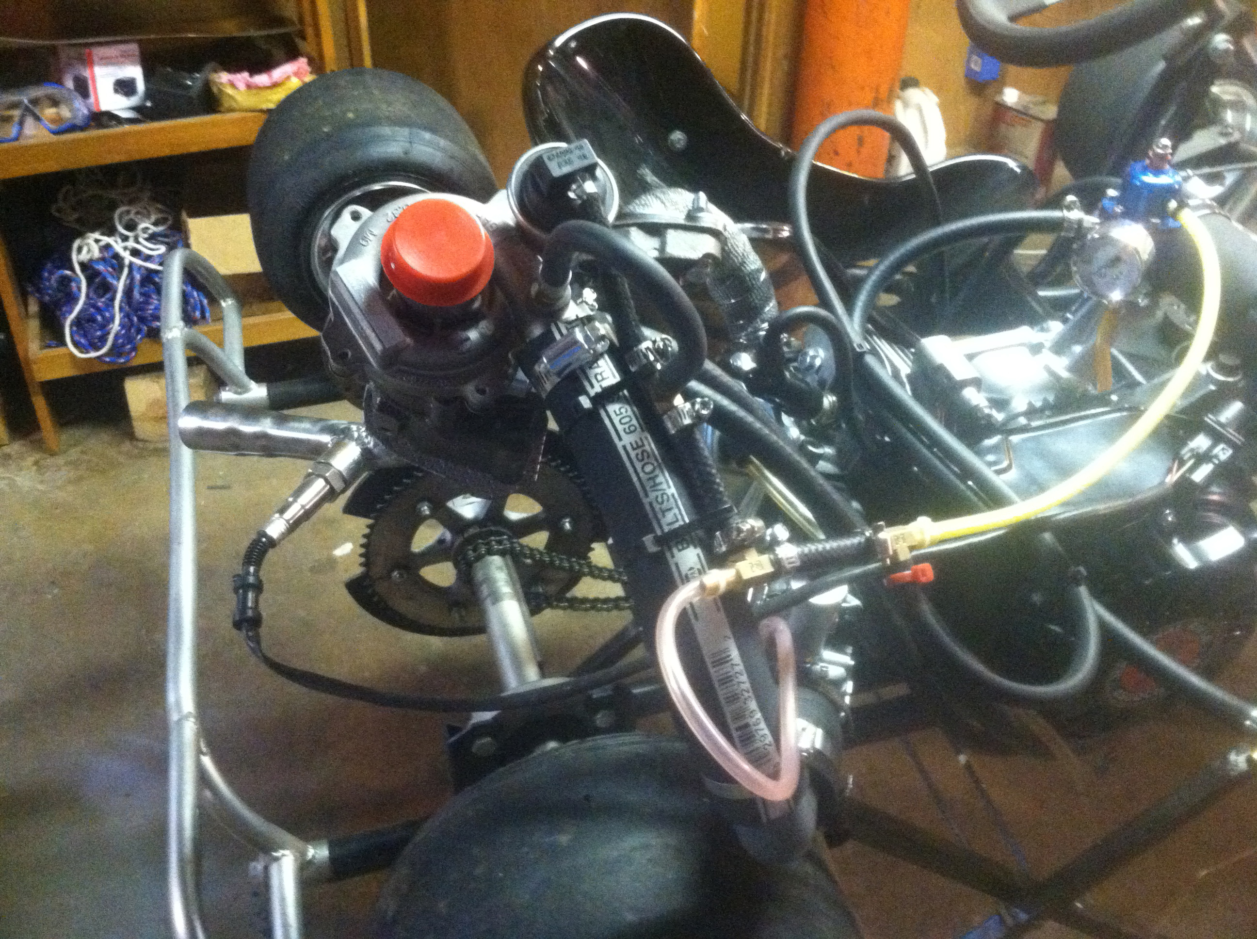
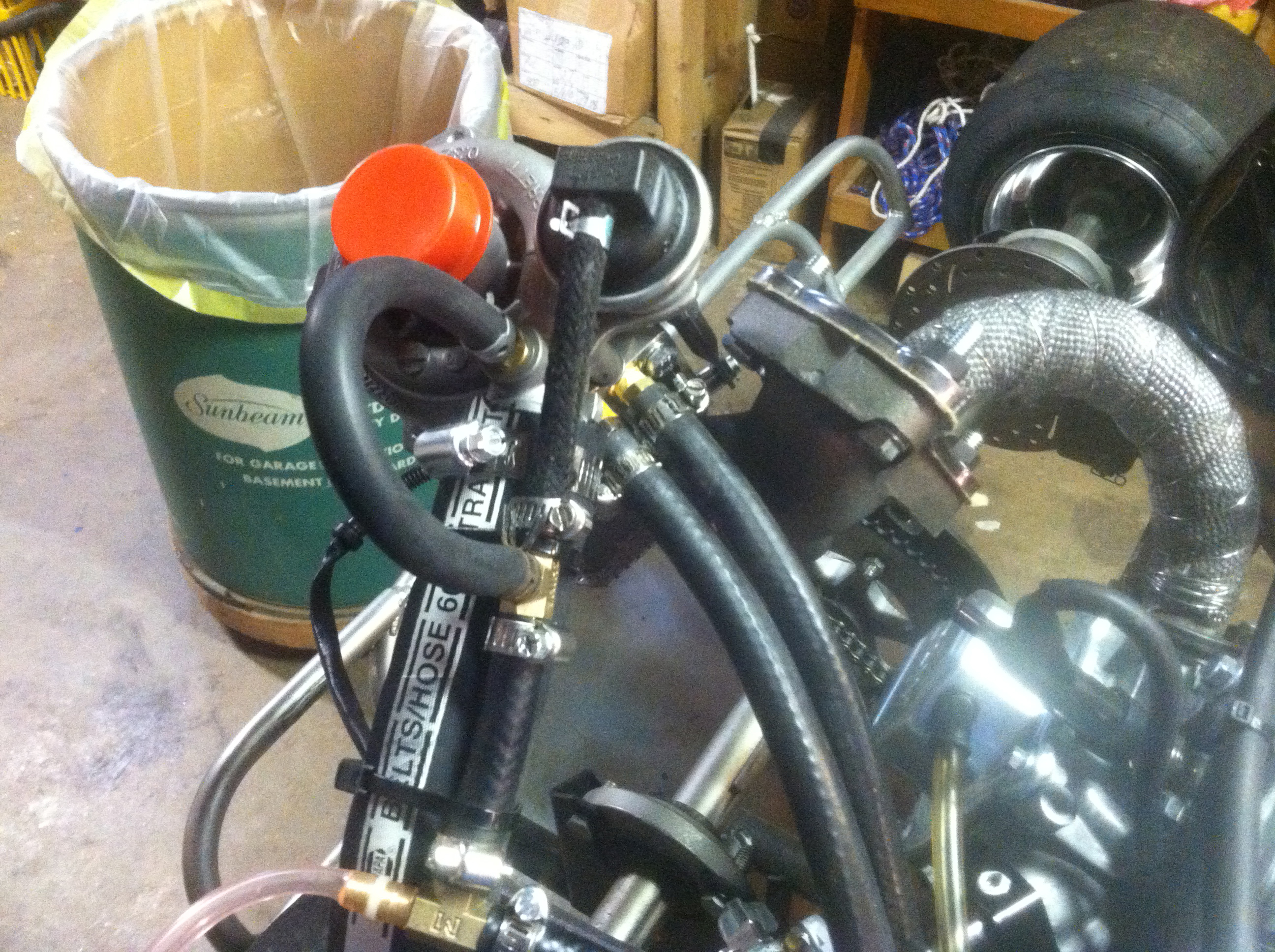
The two hoses under the compressor housing are for the oil inlet and outlet.
The boost can cause other issues like blowing the throttle slide up; this is the equivalent of stomping on the gas! Safety issue, we'll see.
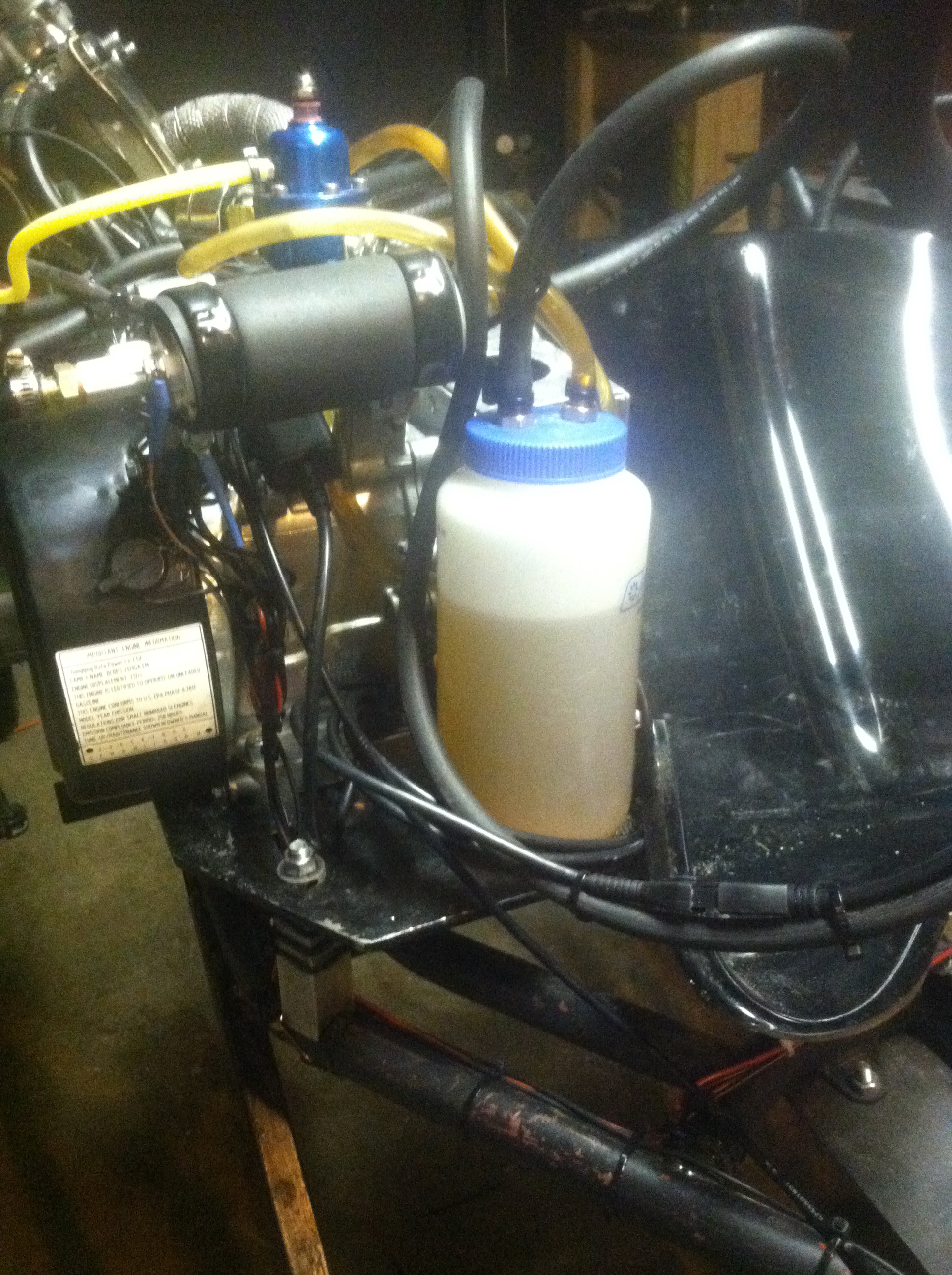
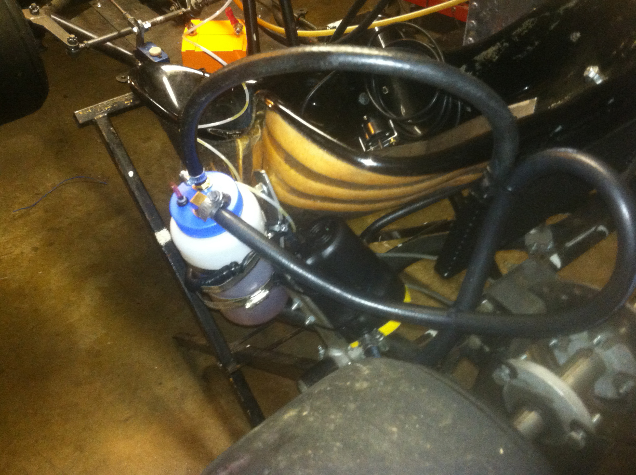
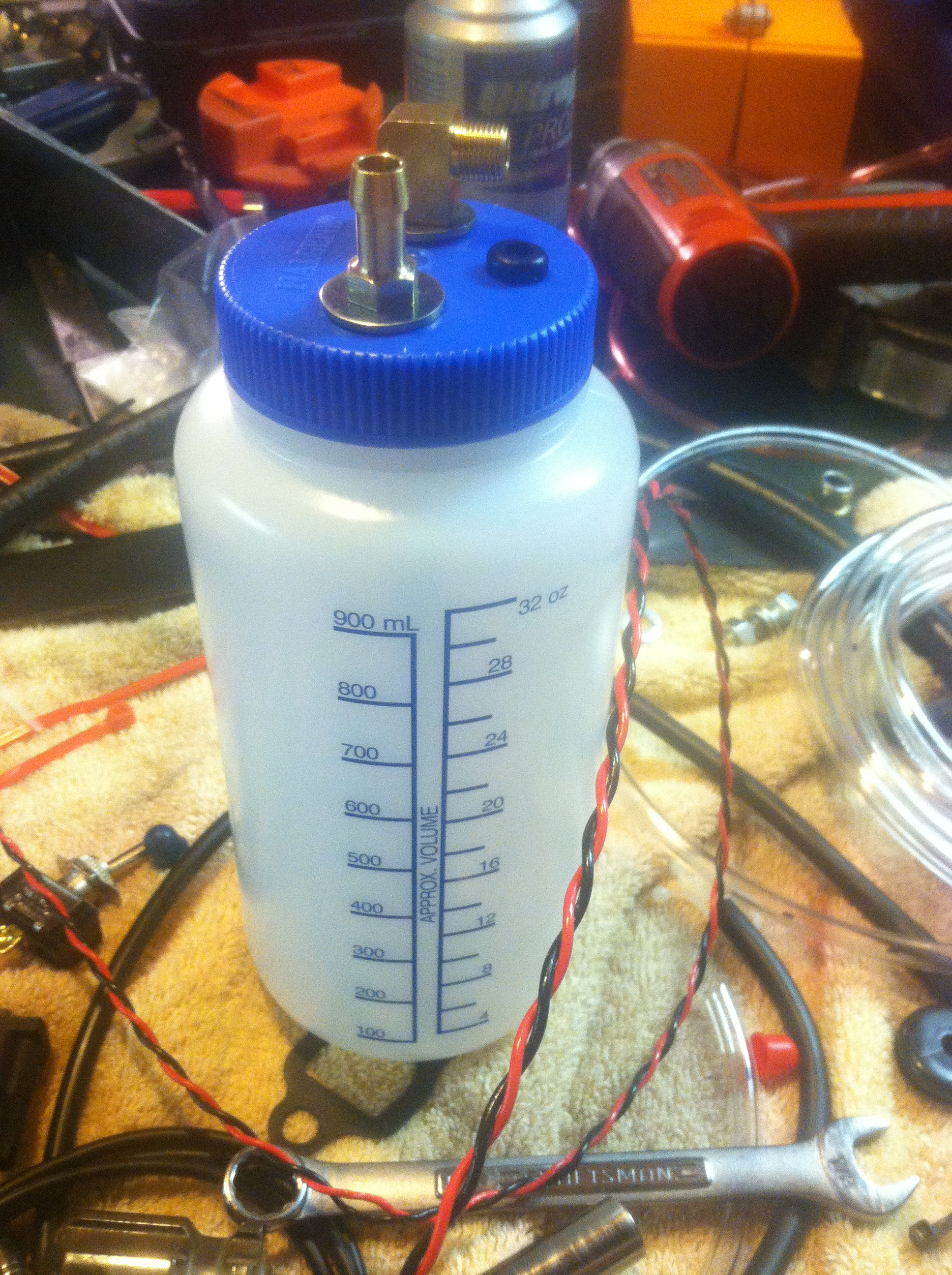
I opted to carry as small an amount of fuel as possible. Using a Nalgene Poly Ethylene water bottle, I have modified the lid with fuel line and brass barb fittings to accept a fuel line and a return line. It works very well on the bench, but as I go farther down this path, it is becoming very apparent that this is a more dangerous project than I previously thought, and should be treated as such.
130 main, 12.5 pilot, 22mm Mikuni VM Carburetor - I might need a 135 or 140 main. 1hp = 1.0143PS
On Fuel Pressure and Mikuni Carbs
On Turbo/Carburetor Setups
Mikuni VM Website
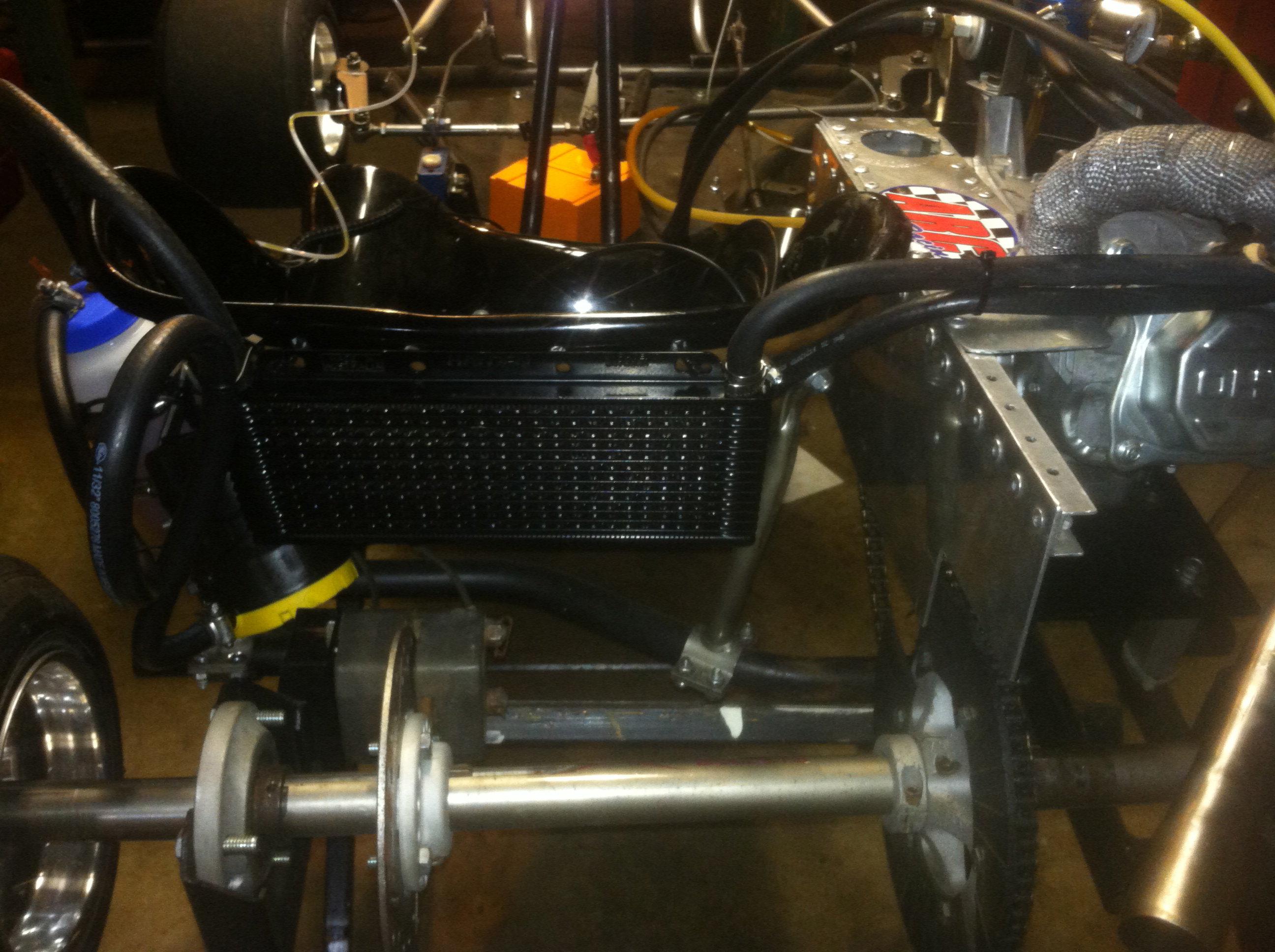
I believe the turbo needs between 10 and 30 PSI. Anything over that and I start seeing oil in the exhaust (blow-by). At first I thought I would send the oil through a cheap Miata transmission oil cooler to help keep the turbo cool. This was a dumb idea because the flow, as it turns out is like 1 gallon/year and oil isn't that great of a coolant anyway. Oh well, this project was started to learn about forced induction, and I'm learning. Anyway I already had the cooler and it does up the oil capacity of the system, so I installed it. I didn't want to spend any more money on this project but my original idea was to use a modified oil catch-can as the oil tank, but I ended up just using a Nalgene poly ethylene water bottle, and it works great!

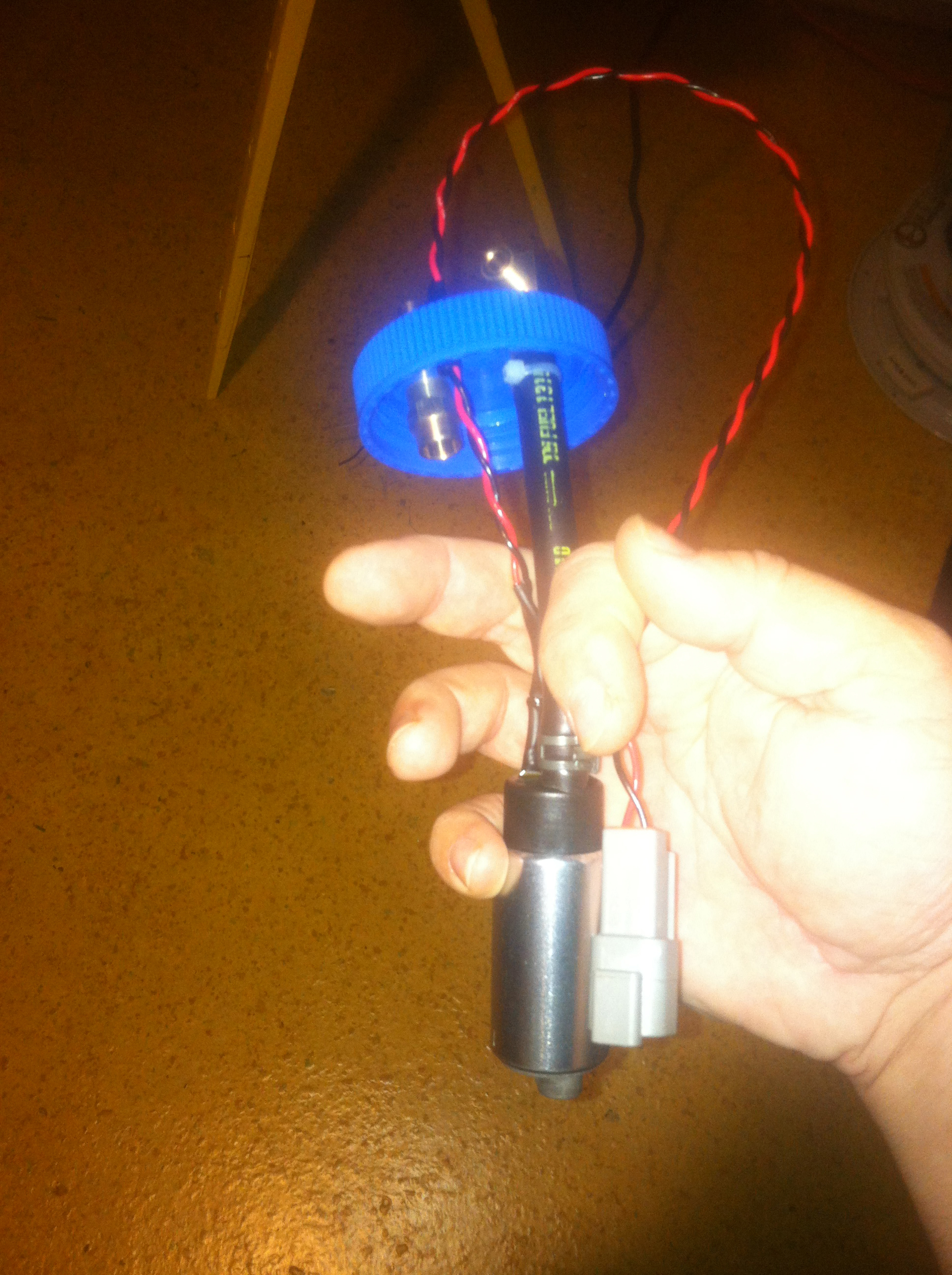
I initially tried to use in-tank cheap fuel pumps to give me oil pressure. They do not work, they just sit there and cavitate and overheat.
The pump was the real issue as typically external, electric, oil pumps are for very high performance (means expensive) applications. What I ended up finding was a Northern Tool oil evacuation pump (like for changing oil in a jet-ski). The pump was 20 bucks online and it will give me 20 PSI! There was a problem though, the pump will literally catch itself on fire by running itself straight to stall. It had been suggested to me to use one of those potentiometer adjusted, PWM controllers, with power transistor output that you can find on Amazon now for like 20 bucks. That really is a great idea and is the way to do it. However, I would have to break my rule and spend more money. So I opted to use a momentary switch that I would manually operate, and bump the switch until I see the oil pressure gauge come back up to 20PSI. It's not tough to keep it between 5 and 25 psi and it was a solution that I made with parts I had laying around.
There is no longer a need for the RPM, or Cam sensors. I am also back to a magneto for ignition. I might need to find some type of advance/retardable ignition system for max boost but so far so good. I have kept the wide-band O2, because it can still help me tune this beast.
Two Failed Oil Pump System Designs
I wanted to engineer in such a way as to ask "what is the safest way to do ____ ?" The control panel starts with a switch that controls a double throw relay that when off, pulls the ignition to ground. Thus if I loose battery, the engine should stop. Further, the relay must be on to power every other electronic system on the kart. So this switch is marked "Kill All" and "Run". This will still not protect me from an engine that ignites from overheating/compression but it will at least cut fuel, even though the engine could, in theory, run a relatively long time on the fuel that is left in the line. However, it's the best I've got for now. When this switch is powered I can actuate an On/Off toggle for the gauge lights that also gives power to the Wide-band O2 sensor's heater. I switched the gauges because the heater can draw a lot of power and it changes my fuel pressure and draws on the battery when I'm just sitting around and wrenching/testing stuff; it's not really a safety issue. I have a momentary switch that I can manually pulse to boost the oil pressure. Then of course I have a maintained switch that controls a relay for the fuel pump. I do not have any fuses installed for this quick and dirty proof of concept. I know, I live on the edge.
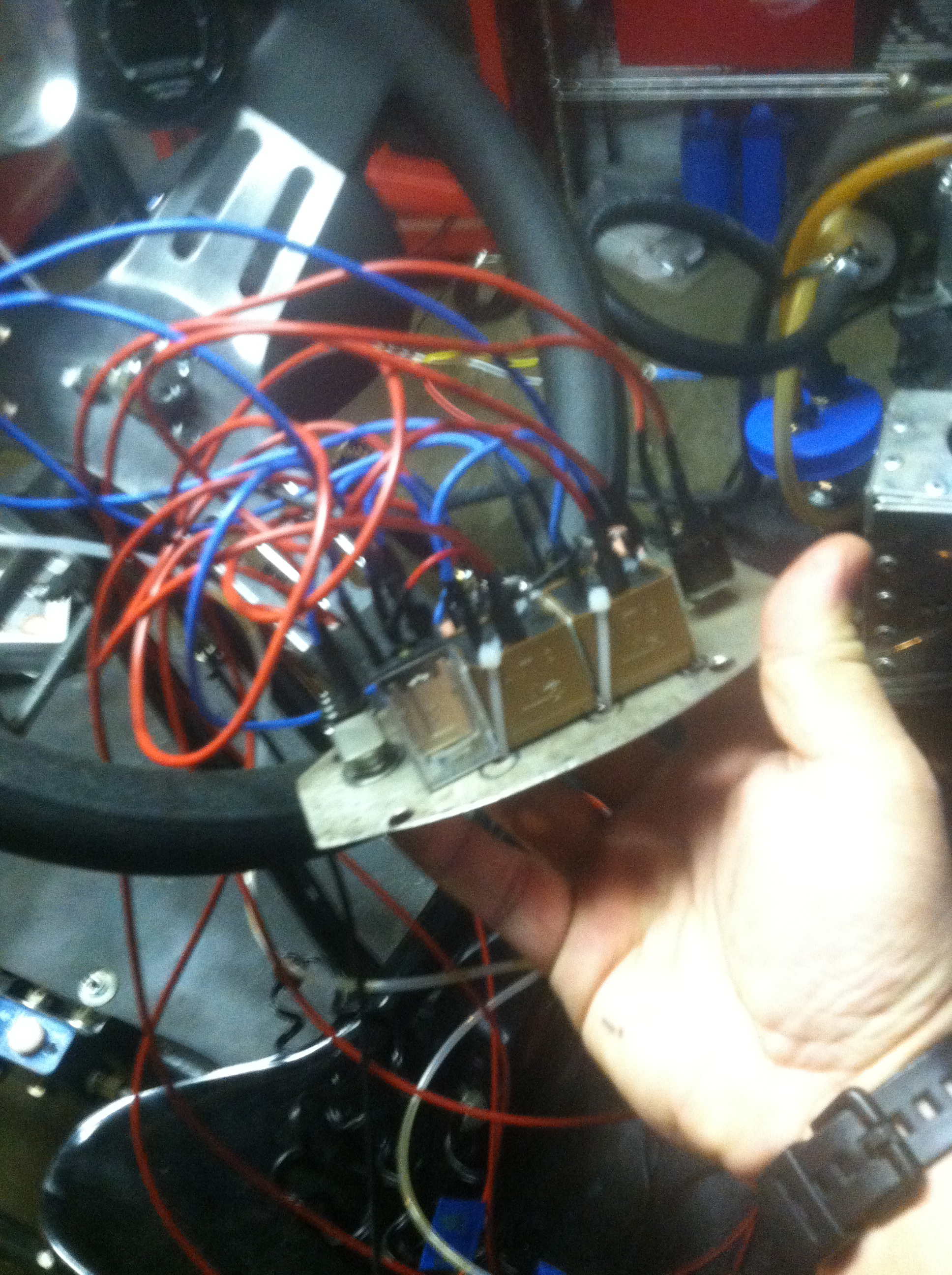
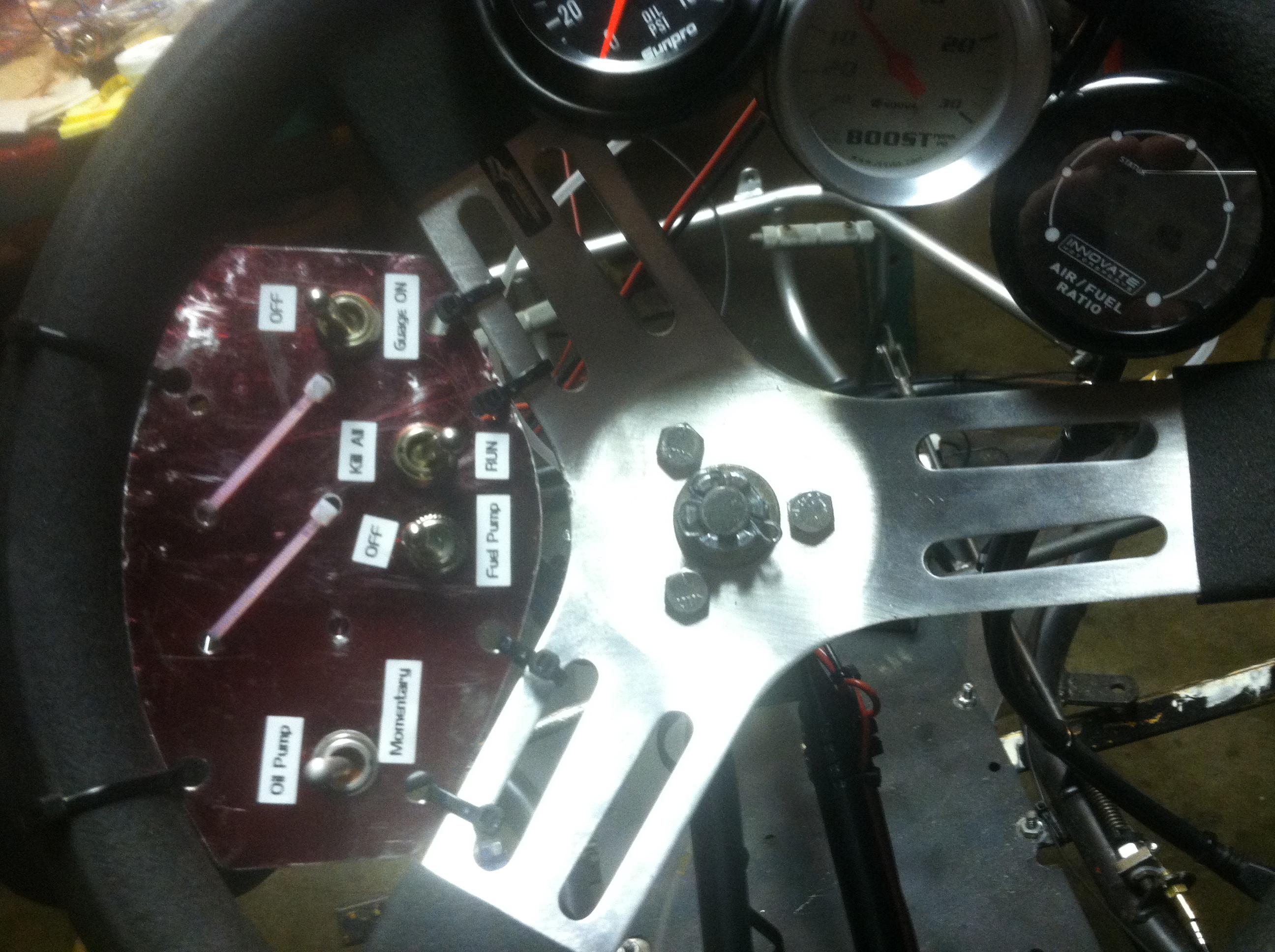
For gauges, I have a charge air boost/vacuum, oil pressure, and wide-band O2 gauge on the steering wheel, and I have the fuel pressure gauge on the fuel pressure regulator. I also have a hand-held RPM gauge that works off of ignition pulse that I might duct-tape somewhere. Remember when using those rpm testers to set it correctly, or divide the raw number by two. Because the unintelligent ignition system of this single cylinder 4 stroke, fires every revolution, even though the ignition stroke takes two revolutions (wasted-spark).