Engine Sensors and Actuators to the Microsquirt
You really need to get a Honda CBR250R Factory Service Manual of the correct year to get what you need to know about the sensors. I found what I needed online and I will list what I know here, but it would have made life easier.
I just taped up a couple of automotive relays for the on/off function of the engine and computer, no innovation here, all the wiring is straight out of the Megasquirt/Microsquirt manual (listed below in Resources). For the fuse block, I simply re-purposed the fuse block from the CBR250R's wiring harness. Buying the wiring harness (used on ebay) really is the way to go.
The TPS sensor can be calibrated from within the TunerStudio software. You just record the maximum closed throttle value then record the maximum open throttle value and TunerStudio does the rest. With the IAT sensor (Intake Air Temperature) it's a little different. If you're using a sensor that's not listed in the software, such is the case with the Honda CBR250R IAT, you must record your own resistance values that the thermistor gives off at different temperatures. I tried putting a digital thermometer and the IAT in the freezer for a while and immediately ran into problems. One, the LCD freezes so you cannot read the temperature. Two, the IAT reacts much faster than my out door thermometer, so the temperature readings do not coincide. You need to take at least three readings to get the thermistor calibrated to the Microsquirt. For my cold reading, I placed a digital meat thermometer along with the IAT sensor in some ice water. When the Meat thermometer stabilized (as much as could be expected) I recorded the temperature and took a resistance reading from the IAT. That was my first calibration point. My second I took in ambient air ( around 70F) and recorded that resistance value. For the third value, I microwaved some water to around 155 and followed the same procedure. This may no be sufficient and it was suggested that I heat motor oil for my high-temp reading... We will see!
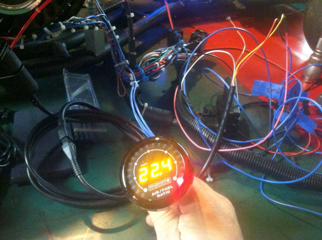
The Innovate Motorsports MTX-L Wide-band O2 sensor is super easy to connect. There is a link below to there website, and their manual is very easy to follow. This thing is SMART too. It has it's own serial interface to program the actual sensor. The Wide-band connects to and is controlled by the gauge. The gauge is actual LED's not LCD's, so you can view it even with polarized sunglasses on. I set mine up with the Yellow wire to the Microsquirt. The yellow wire outputs 0 volts for 7.35 AFR and 5 volts for 22.39 AFR. The gauge itself can output (and display) either AFR or Lambda. It wants a 5 amp fuse in line with the power connection! This is because the physical sensor has a heater to provide accurate readings before the exhaust is at full temperature.
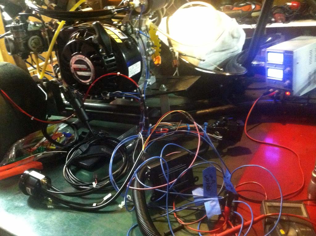
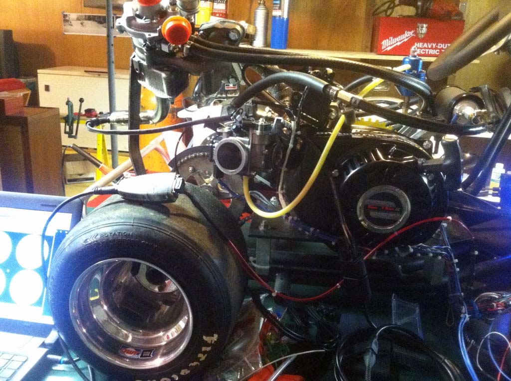
Just a simple setup for testing, I opted to use a power supply instead of a battery. The PS I'm using wimps out at around 3 amps so I pulled the fuse on the fuel pump. It is normally controlled by the Microsquirt, but I'm not at that phase in the testing yet. I should also note that in some of the pics, it looks like a few of the fuel lines and wires are touching the turbo....They're not.
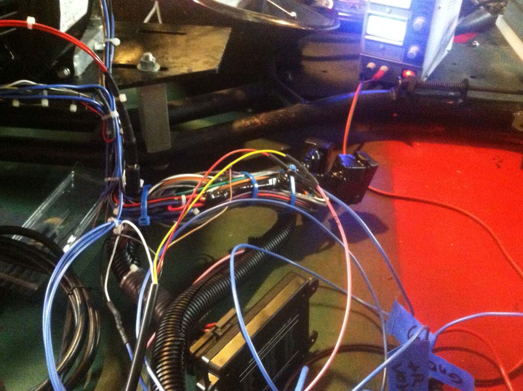
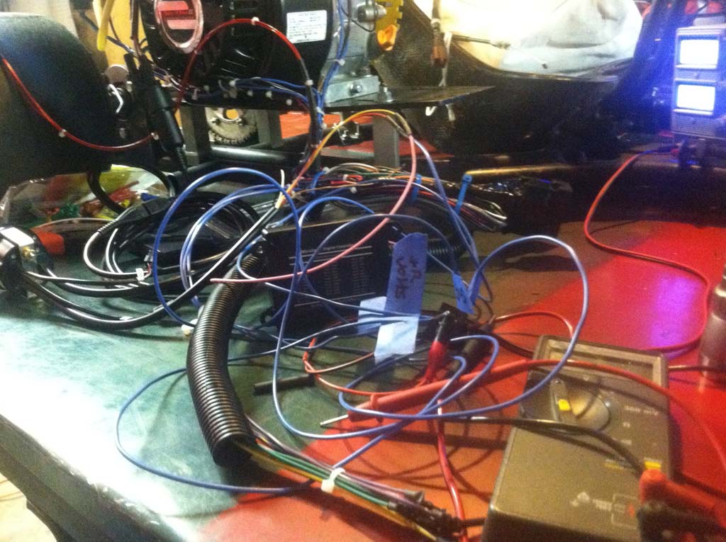
I know it's messy, I gave myself a lot of wire to work with. I also did not want to cut the (very nice) wiring harness wires that came with the Microsquirt. This gave me lots of room to work, and re-work my wiring. It was such a mess I just put it all together and took pictures after the fact. I needed full concentration to make sure I wired it exactly as I had drawn it. It's not rocket science, you just must be methodical.
You need to print out all the wiring material so it can be right next to you while you are actually doing the wiring and also, so you can write notes on the sheets. I labeled everything with a Sharpie and some masking tape, there are just too many wires not to. Also, I had a limited number of wire colors in my inventory to use so, (I know it's bad) I had a lot of signal, power, and ground wires, all the same color.
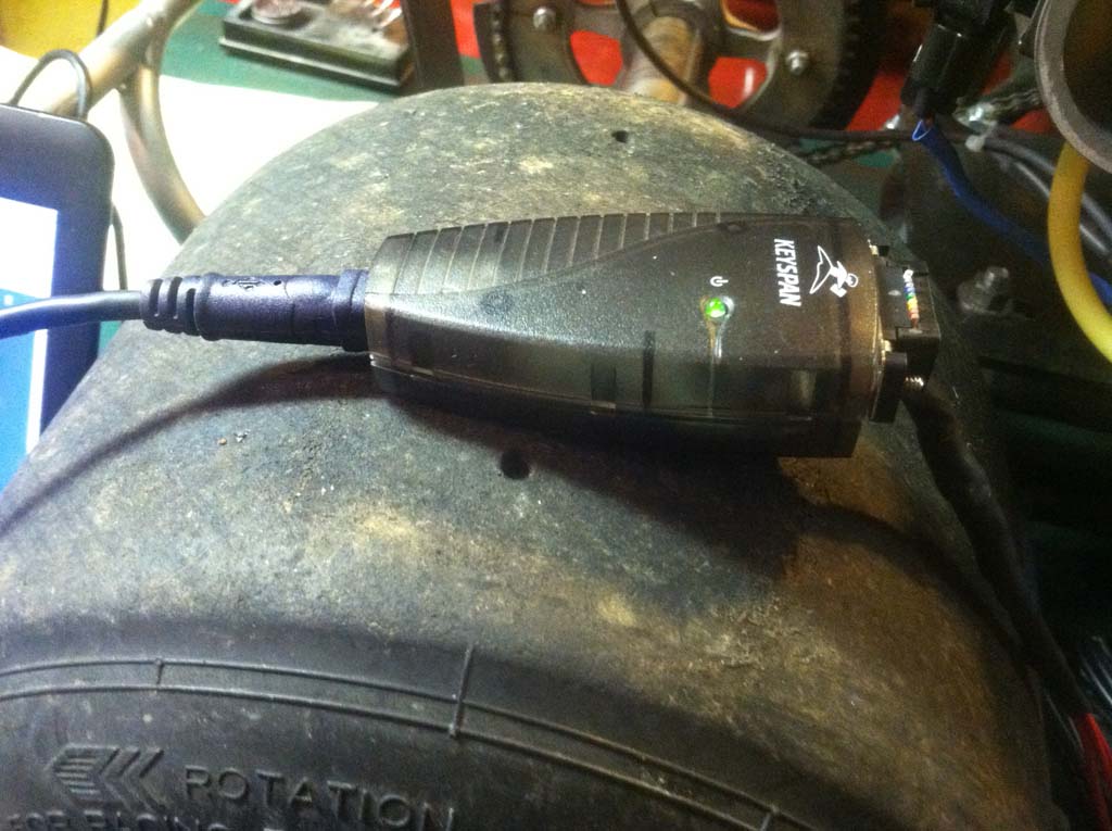
MicroSquirt to the Computer
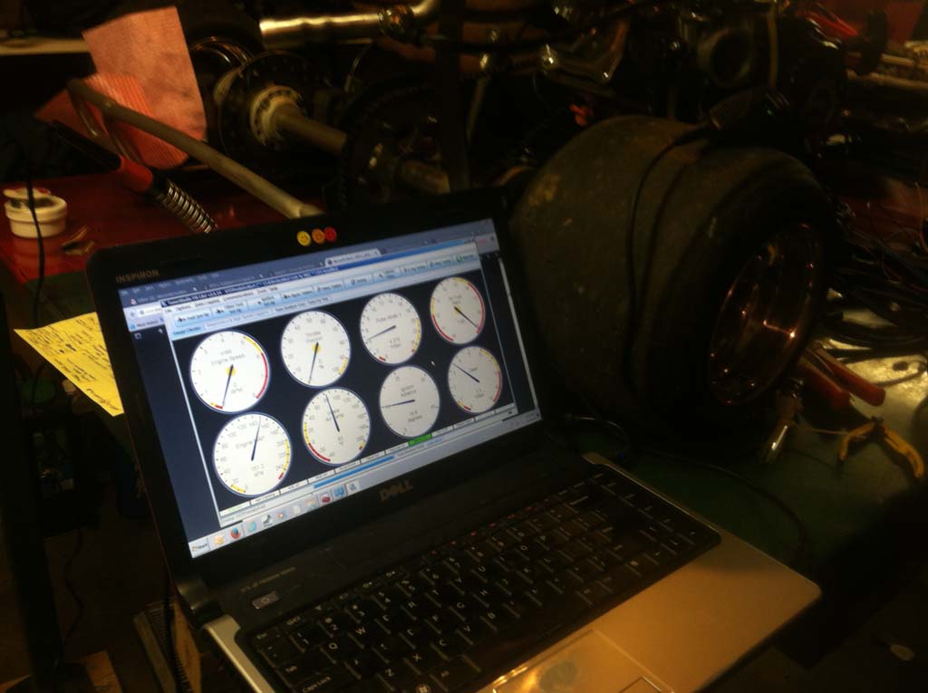
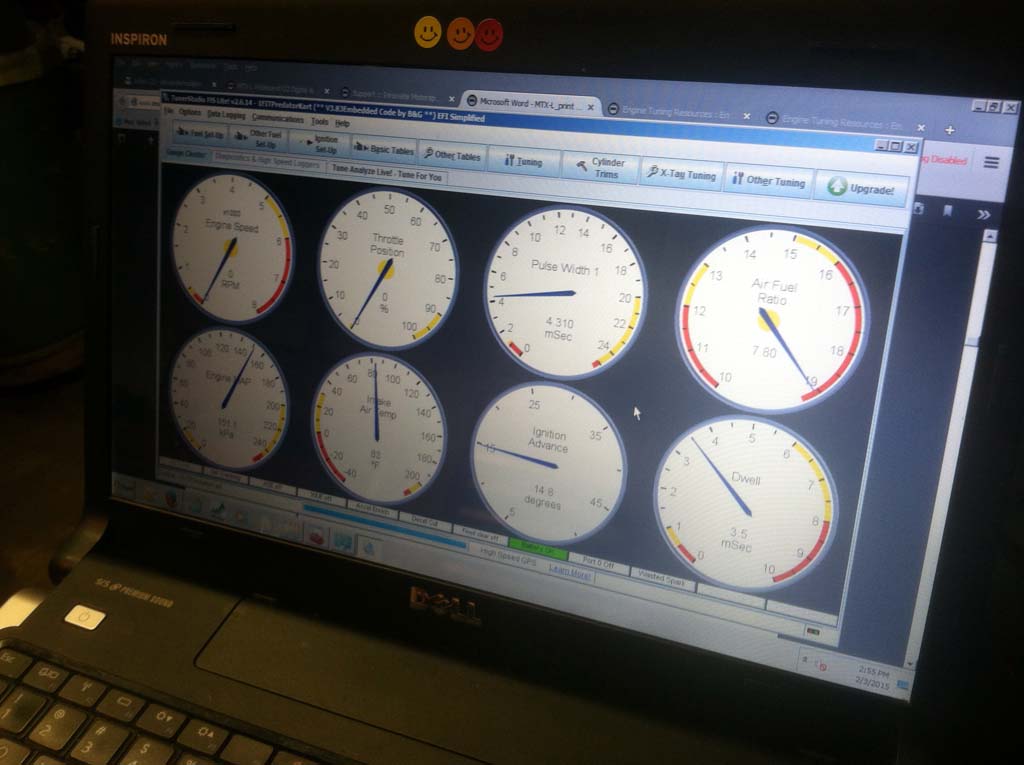
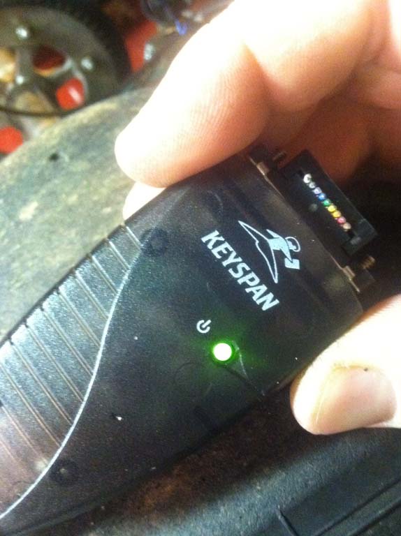
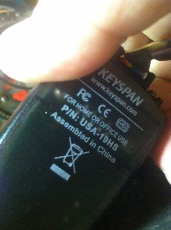
These pics are of the TunerStudio software running and the USB to RS232 adapter I used. All RS232 adapters are not created equal. The best ones seem to contain the MAX232 chip. The Keyspan one works very well. It should also be noted that I have disconnected the ignition module for this phase of the build. I'd hate to burn it out early, before I get a chance to tune it.